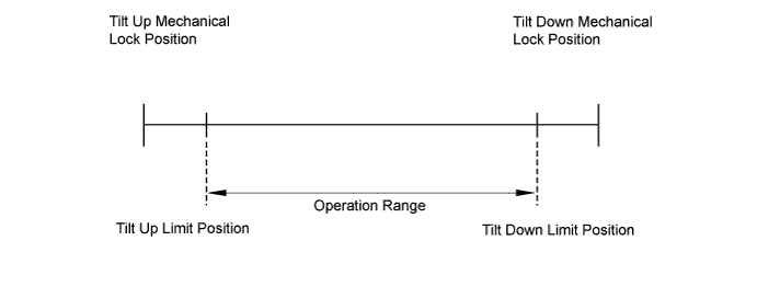
DTC B2610 Tilt Position Sensor or Tilt Motor Circuit Malfunction |
| DTC Code | Detection Condition | Trouble Area |
| B2610 | Tilt operation stops within the operation range while operating. |
|
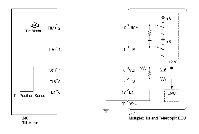
| 1.PERFORM ACTIVE TEST USING TECHSTREAM (TILT UP/DOWN) |
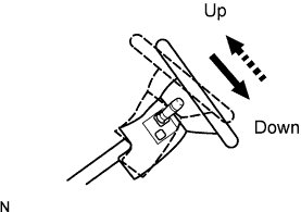 |
Select the Active Test, use the Techstream to generate a control command, and then check that the steering wheel tilt up and down.
| Tester Display | Test Part | Control Range | Diagnostic Note |
| Tilt operation | Tilt operation | Up / Down | - |
| Result | Proceed to |
| Steering wheel does not tilt up (down). | A |
| Steering wheel tilts up (down). | B |
|
| ||||
| A | |
 |
| 2.CHECK HARNESS AND CONNECTOR (MULTIPLEX TILT AND TELESCOPIC ECU - TILT MOTOR) |
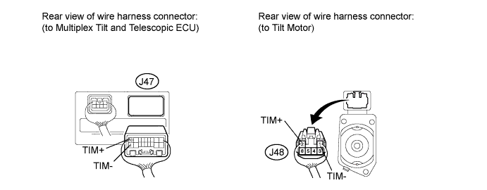
Disconnect the J47 multiplex tilt and telescopic ECU connector.
Disconnect the J48 tilt motor connector.
Measure the resistance according to the value(s) in the table below.
| Tester Connection | Condition | Specified Condition |
| J47-10 (TIM+) - J48-2 (TIM+) | Always | Below 1 Ω |
| J47-1 (TIM-) - J48-1 (TIM-) | Always | Below 1 Ω |
| J47-10 (TIM+) - Body ground | Always | 10 kΩ or higher |
| J47-1 (TIM-) - Body ground | Always | 10 kΩ or higher |
|
| ||||
| OK | |
|
| 3.INSPECT TILT MOTOR |
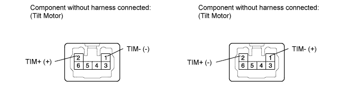
Apply 12 V battery voltage to the tilt motor connector. Then check the steering wheel tilt operation.
| Measurement Condition | Specified Condition |
| 12 V battery positive (+) lead → Terminal 2 (TIM+) 12 V battery negative (-) lead → Terminal 1 (TIM-) | The steering wheel tilts up. |
| 12 V battery positive (+) lead → Terminal 1 (TIM-) 12 V battery negative (-) lead → Terminal 2 (TIM+) | The steering wheel tilts down. |
|
| ||||
| OK | ||
 | ||
| ||
| 4.CHECK HARNESS AND CONNECTOR (MULTIPLEX TILT AND TELESCOPIC ECU - TILT POSITION SENSOR) |
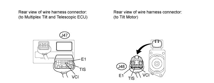
Disconnect the J47 multiplex tilt and telescopic ECU connector.
Disconnect the J48 tilt motor connector.
Measure the resistance according to the value(s) in the table below.
| Tester Connection | Condition | Specified Condition |
| J47-6 (VCI) - J48-4 (VCI) | Always | Below 1 Ω |
| J47-7 (TIS) - J48-5 (TIS) | Always | Below 1 Ω |
| J47-17 (E1) - J48-6 (E1) | Always | Below 1 Ω |
| J47-6 (VCI) - Body ground | Always | 10 kΩ or higher |
| J47-7 (TIS) - Body ground | Always | 10 kΩ or higher |
| J47-17 (E1) - Body ground | Always | 10 kΩ or higher |
|
| ||||
| OK | |
|
| 5.CHECK HARNESS AND CONNECTOR (MULTIPLEX TILT AND TELESCOPIC ECU - BODY GROUND) |
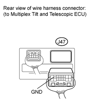 |
Measure the resistance according to the value(s) in the table below.
| Tester Connection | Condition | Specified Condition |
| J47-11 (GND) - Body ground | Always | Below 1 Ω |
|
| ||||
| OK | |
|
| 6.CHECK MULTIPLEX TILT AND TELESCOPIC ECU (VCI, TIS TERMINAL VOLTAGE) |
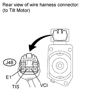 |
Reconnect the J47 multiplex tilt and telescopic ECU connector.
Measure the voltage according to the value(s) in the table below.
| Tester Connection | Switch Condition | Specified Condition |
| J48-4 (VCI) - J48-6 (E1) | Ignition switch ON | 8 to 16 V |
| J48-5 (TIS) - J48-6 (E1) | Ignition switch ON | 8 to 16 V |
|
| ||||
| OK | |
|
| 7.CHECK TILT POSITION SENSOR |
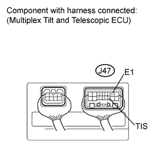 |
Reconnect the J48 tilt motor connector.
Measure the voltage according to the value(s) in the table below.
| Tester Connection | Condition | Specified Condition |
| J47-7 (TIS) - J47-17 (E1) | Steering tilts up or tilts down | Pulse generation High: 8 to 16 V Low: Below 1 V |
|
| ||||
| OK | ||
| ||
| ||

