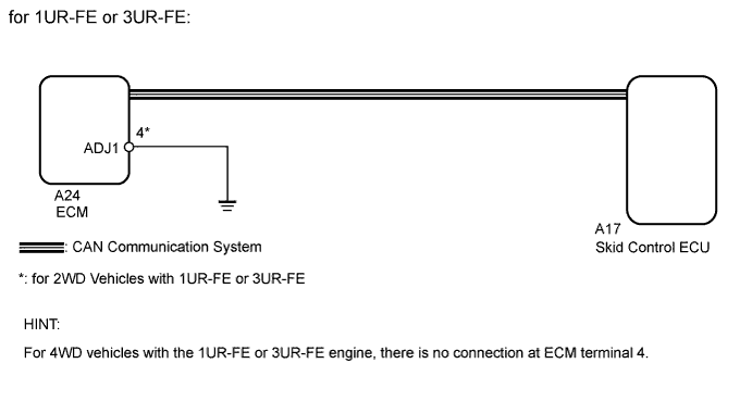
DTC C1370/73 Engine or Transmission System Matching Error |
| DTC Code | DTC Detection Condition | Trouble Area |
| C1370/73 | Information relating to engine, transmission, drivetrain or destination stored in ECM does not match information stored in skid control ECU. |
|
| 1.READ VALUE USING TECHSTREAM (ENGINE TYPE) |
Turn the ignition switch off.
Connect the Techstream to the DLC3.
Turn the ignition switch to ON.
Turn the Techstream on.
Enter the following menus: Powertrain / Engine and ECT / Data List.
According to the display on the Techstream, use the Data List.
| Tester Display | Measurement Item/Range | Normal Condition | Diagnostic Note |
| Engine Type | Engine type | Engine type information stored in currently installed ECM displayed | - |
Check that the installed engine type and the engine type information stored in the ECM match by reading the Data List.
| Result | Proceed to |
| OK (1UR-FE, 3UR-FE) | A |
| OK (1GR-FE, 3UR-FBE) | B |
| NG | C |
|
| ||||
|
| ||||
| A | |
 |
| 2.READ VALUE USING TECHSTREAM (VEHICLE SPEC SIG 1) |
Turn the ignition switch off.
Connect the Techstream to the DLC3.
Turn the ignition switch to ON.
Turn the Techstream on.
Enter the following menus: Powertrain / Engine and ECT / Data List.
According to the display on the Techstream, use the Data List.
| Tester Display | Measurement Item/Range | Normal Condition | Diagnostic Note |
| Vehicle Spec Signal 1 | Information indicating if vehicle is 2WD or 4WD/ ON or OFF | ON: 2WD OFF: 4WD | - |
Check that the actual vehicle type and the information read from the Data List match.
| Result | Proceed to |
| Actual vehicle type and information read from Data List do not match | A |
| Actual vehicle type and information read from Data List match | B |
|
| ||||
| A | |
|
| 3.CHECK HARNESS AND CONNECTOR (ECM - BODY GROUND) |
for 4WD:
Check that terminal 4 of the ECM for connector A24 does not have a wire harness connection and is not connected to ground.
for 2WD:
Check that terminal 4 of the ECM for connector A24 has a wire harness connection.
Disconnect the ECM connector.
Measure the resistance according to the value(s) in the table below.
| Tester Connection | Condition | Specified Condition |
| A24-4 (ADJ1) - Body ground | Always | Below 1 Ω |
| Result | Proceed to |
| for 4WD: Terminal 4 of the ECM for connector A24 is connected to ground for 2WD: Wire harness is open | A |
| for 4WD: Terminal 4 of the ECM for connector A24 is not connected to ground for 2WD: Wire harness is not open and is connected to ground | B |
|
| ||||
| A | |
|
| 4.REPAIR OR REPLACE HARNESS OR CONNECTOR |
Repair or replace harness or connector.
| NEXT | |
|
| 5.READ VALUE USING TECHSTREAM (VEHICLE SPEC SIG 1) |
Turn the ignition switch off.
Connect the Techstream to the DLC3.
Turn the ignition switch to ON.
Turn the Techstream on.
Enter the following menus: Powertrain / Engine and ECT / Data List.
According to the display on the Techstream, use the Data List.
| Tester Display | Measurement Item/Range | Normal Condition | Diagnostic Note |
| Vehicle Spec Signal 1 | Information indicating if vehicle is 2WD or 4WD/ ON or OFF | ON: 2WD OFF: 4WD | - |
Check that the actual vehicle type and the information read from the Data List match.
| Result | Proceed to |
| Actual vehicle type and information read from Data List do not match | A |
| Actual vehicle type and information read from Data List match | B |
|
| ||||
| A | |
|
| 6.REPLACE ECM |
Replace the ECM for 1GR-FE (Click here), 1UR-FE (Click here), 3UR-FE (Click here) or 3UR-FBE (Click here).
| NEXT | |
|
| 7.RECONFIRM DTC |
Clear the DTC (Click here).
Check if the same DTC is output (Click here).
| Result | Proceed to |
| DTC is output | A |
| DTC is not output | B |
|
| ||||
| A | ||
 | ||
| ||
| 8.RECONFIRM DTC |
Clear the DTC (Click here).
Check if the same DTC is output (Click here).
| Result | Proceed to |
| DTC is output | A |
| DTC is not output | B |
|
| ||||
| A | ||
| ||
| ||

