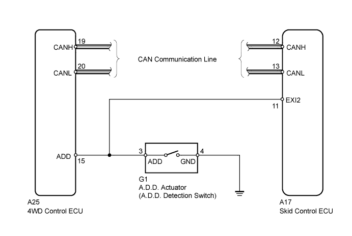
DTC C1340/47 Center Differential Lock Circuit |
| DTC Code | DTC Detection Condition | Trouble Area |
| C1340/47 | When the terminal IG1 voltage is between 10 and 14 V, there is an open in the A.D.D. detection switch circuit or there is a transfer mechanical malfunction for 2 seconds or more. |
|
| 1.INSPECT SKID CONTROL ECU (EXI2 TERMINAL) |
Set the vehicle in 4WD state using the A.D.D. detection switch.
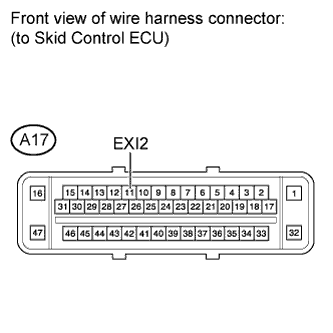 |
Disconnect the A17 ECU connector.
Turn the ignition switch to ON.
Measure the voltage according to the value(s) in the table below.
| Tester Connection | Switch Condition | Specified Condition |
| A17-11 (EXI2) - Body ground |
| Below 1.5 V |
Connect the A17 ECU connector.
Set the vehicle in 2WD state using the A.D.D. detection switch.
Disconnect the A17 ECU connector.
Turn the ignition switch to ON.
Measure the voltage according to the value(s) in the table below.
| Tester Connection | Switch Condition | Specified Condition |
| A17-11 (EXI2) - Body ground |
| 10 to 14 V |
|
| ||||
| OK | ||
 | ||
| ||
| 2.CHECK HARNESS AND CONNECTOR (SKID CONTROL ECU - 4WD CONTROL ECU) |
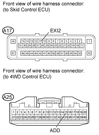 |
Confirm that the skid control ECU connector and 4WD control ECU connector are properly connected.
Disconnect the A17 and A25 ECU connectors.
Disconnect the G1 A.D.D. actuator connector.
Inspect both the connector case and the terminal for deformation and corrosion.
Measure the resistance according to the value(s) in the table below.
| Tester Connection | Condition | Specified Condition |
| A17-11 (EXI2) - A25-15 (ADD) | Always | Below 1 Ω |
| A17-11 (EXI2) - Body ground | Always | 10 kΩ or higher |
|
| ||||
| OK | |
 |
| 3.CHECK HARNESS AND CONNECTOR (4WD CONTROL ECU - BODY GROUND) |
Confirm that the 4WD control ECU connector and A.D.D. actuator connectors are properly connected.
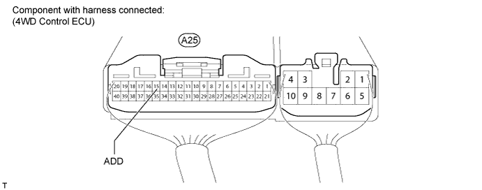
Disconnect the A25 ECU connector.
Inspect the connector case and the terminal for deformation and corrosion.
Connect the A25 ECU connector.
Measure the resistance according to the value(s) in the table below.
| Tester Connection | Switch Condition | Specified Condition |
| A25-15 (ADD) - Body ground | 4WD (A.D.D. detection switch ON) | Below 1 Ω |
| 2WD (A.D.D. detection switch OFF) | 10 kΩ or higher |
|
| ||||
| OK | |
|
| 4.RECONFIRM DTC |
Clear the DTC(s) (Click here).
Start the engine.
Check if the same DTC(s) is output (Click here).
| Result | Proceed to |
| DTC is output | A |
| DTC is not output | B |
|
| ||||
| A | ||
| ||
| ||

