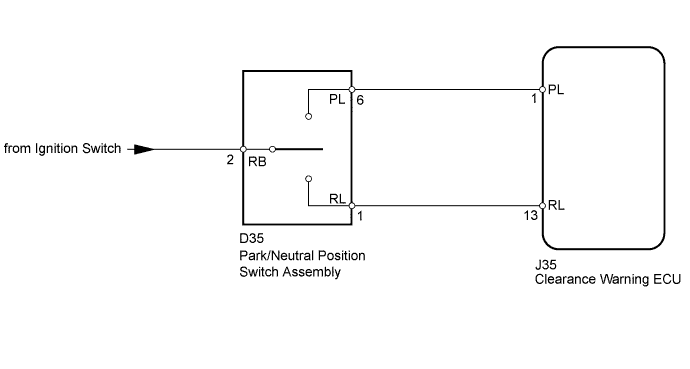
INTUITIVE PARKING ASSIST SYSTEM > Park / Neutral Position Switch Circuit |
| 1.INSPECT PARK/NEUTRAL POSITION SWITCH ASSEMBLY |
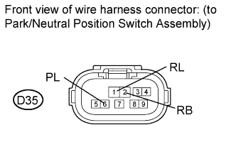 |
Disconnect the D35 switch connector.
Measure the resistance according to the value(s) in the table below.
| Tester Condition | Condition | Specified Condition |
| 6 (PL) - 2 (RB) | Shift lever on P | Below 1 Ω |
| 1 (RL) - 2 (RB) | Shift lever on R | Below 1 Ω |
| 6 (PL) - 2 (RB) | Shift lever not on P | 10 kΩ or higher |
| 1 (RL) - 2 (RB) | Shift lever not on R | 10 kΩ or higher |
|
| ||||
| OK | |
 |
| 2.CHECK HARNESS AND CONNECTOR (PARK/NEUTRAL POSITION SWITCH - CLEARANCE WARNING ECU) |
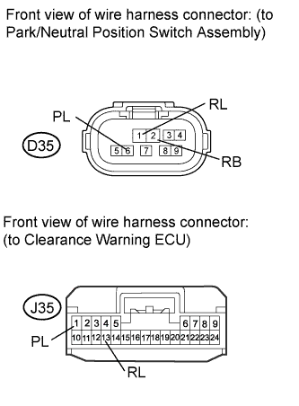 |
Disconnect the D35 park/neutral position switch assembly connector.
Disconnect the J35 clearance warning ECU connector.
Measure the voltage according to the value(s) in the table below.
| Tester Condition | Switch Condition | Specified Condition |
| D35-2 (RB) - Body ground | Ignition switch ON | 11 to 14 V |
Measure the resistance according to the value(s) in the table below.
| Tester Condition | Condition | Specified Condition |
| D35-6 (PL) - J35-1 (PL) | Always | Below 1 Ω |
| D35-1 (RL) - J35-13 (RL) | Always | Below 1 Ω |
| D35-6 (PL) - Body ground | Always | 10 kΩ or higher |
| D35-1 (RL) - Body ground | Always | 10 kΩ or higher |
|
| ||||
| OK | ||
 | ||
| ||
