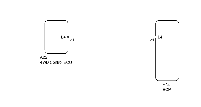
DTC P2772 Four Wheel Drive (4WD) Low Switch Circuit Range / Performance |
| DTC Code | DTC Detection Condition | Trouble Area |
| P2772 | Transfer 4L position switch remains ON while vehicle is running under following conditions for 1.8 sec. or more (1-trip detection logic) (a) Output shaft speed between 1000 and 3000 rpm (b) Transfer position switch is in 4H |
|
| Related DTCs | P2772: Transfer 4L position switch/Functional check |
| Required sensors/Components | Transfer 4L position switch |
| Frequency of operation | Continuous |
| Duration | ON malfunction (A): 1.8 seconds ON malfunction (B): 0.5 seconds |
| MIL operation | 1 driving cycle |
| Sequence of operation | None |
| The monitor will run whenever the following DTCs are not present | P0500 (Output speed sensor circuit) P0722 (Vehicle speed sensor circuit) |
| Transfer neutral position switch | OFF |
| Output speed (Transfer output speed) | 1000 to 3000 rpm |
| Output speed (Transfer output speed) | 143 rpm or more |
| 4L switch | ON |
| Actual transfer gear ratio Transfer input speed/Transfer output speed | 0.9 or more, and less than 1.1 |
| 1.CHECK HARNESS AND CONNECTOR (4WD CONTROL ECU - BODY GROUND) |
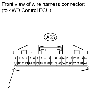 |
Disconnect the A25 4WD control ECU connector.
Measure the resistance according to the value(s) in the table below.
| Tester Connection | Condition | Specified Condition |
| A25-21 (L4) - Body ground | Always | 10 kΩ or higher |
| Result | Proceed to |
| NG | A |
| OK | B |
|
| ||||
| A | |
 |
| 2.CHECK HARNESS AND CONNECTOR (4WD CONTROL ECU - ECM) |
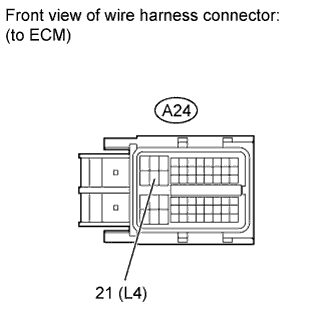 |
Disconnect the A24 ECM connector.
Measure the resistance according to the value(s) in the table below.
| Tester Connection | Condition | Specified Condition |
| A24-21 (L4) - Body ground | Always | 10 kΩ or higher |
| Result | Proceed to |
| NG | A |
| OK (for 3UR-FE) | B |
| OK (for 3UR-FBE) | C |
|
| ||||
|
| ||||
| A | ||
 | ||
| ||
