 |
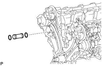
Apply soapy water to 2 new O-rings and install them to the inlet pipe.
OIL PUMP > INSTALLATION |
| 1. INSTALL WATER INLET PIPE |
|
Apply soapy water to 2 new O-rings and install them to the inlet pipe.
Install the inlet pipe to the No. 1 heat exchanger cover.
| 2. INSTALL TIMING CHAIN COVER SUB-ASSEMBLY |
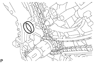 |
Apply a light coat of engine oil to a new oil pump gasket.
Install the oil pump gasket.
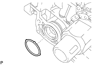 |
Apply a light coat of engine oil to a new O-ring.
Install the O-ring.
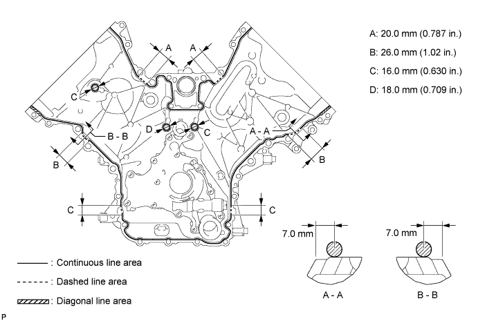
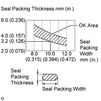
Apply seal packing in a continuous line to the timing chain cover as shown in the following illustration.
 |
| Area | Seal Packing Diameter | Application Position from Inside Edge of Cover |
| Continuous Line Area | 3.0 to 4.0 mm (0.118 to 0.157 in.) | 2.5 mm (0.0984 in.) |
| Dashed Line Area | 6.4 mm (0.252 in.) or more, or within OK area shown in illustration | 7.0 mm (0.276 in.) |
| Diagonal Line Area | 3.0 to 4.0 mm (0.118 to 0.157 in.) | 5.5 mm (0.217 in.) |
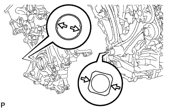 |
Align the oil pump drive rotor spline and crankshaft as shown in the illustration and install the chain cover.
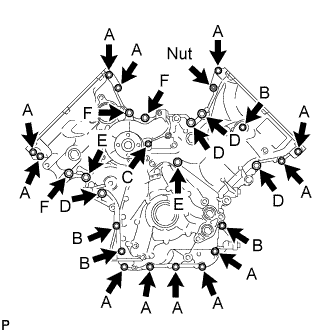 |
Temporarily install the 26 bolts and nut.
| Item | Length | Thread Diameter |
| Bolt A | 25 mm (0.984 in.) | 8 mm (0.315 in.) |
| Bolt B | 55 mm (2.17 in.) | 8 mm (0.315 in.) |
| Bolt C | 70 mm (2.76 in.) | 8 mm (0.315 in.) |
| Bolt D | 35 mm (1.38 in.) | 10 mm (0.394 in.) |
| Bolt E | 55 mm (2.17 in.) | 10 mm (0.394 in.) |
| Bolt F | 80 mm (3.15 in.) | 10 mm (0.394 in.) |
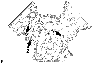 |
Tighten the 3 bolts in several steps in the sequence shown in the illustration.
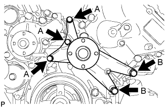 |
Temporarily install the fan bracket with the 5 bolts.
| Item | Length | Thread Diameter |
| Bolt A | 70 mm (2.76 in.) | 8 mm (0.315 in.) |
| Bolt B | 80 mm (3.15 in.) | 10 mm (0.394 in.) |
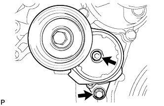 |
Temporarily install the belt tensioner with the bolt and 6 mm hexagon bolt.
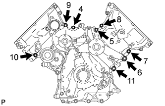 |
Tighten the 8 bolts labeled 4 to 11 in several steps in the sequence shown in the illustration.
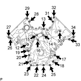 |
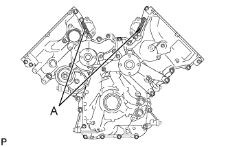
Tighten the 23 bolts and nut labeled 12 to 34 in several steps in the sequence shown in the illustration.
 |
| 3. INSTALL FRONT CRANKSHAFT OIL SEAL |
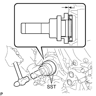 |
Apply MP grease to the lip of a new oil seal.
Using SST and a hammer, tap in the oil seal to a depth between 0 to 1.0 mm (0 to 0.0394 in.) from the timing chain cover edge.
| 4. INSTALL CYLINDER HEAD COVER SUB-ASSEMBLY LH |
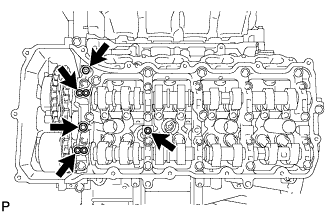 |
Install 5 new gaskets to the camshaft bearing caps (No. 2, No. 3).
Install the cover gasket to the cylinder head cover.
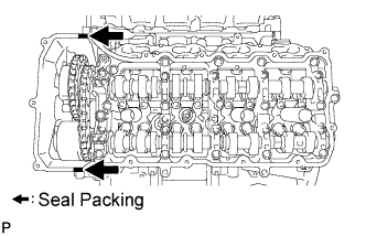 |
Apply seal packing as shown in the illustration.
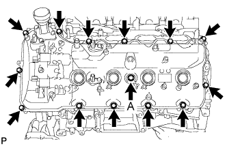 |
Install the cylinder head cover and a new seal washer with the 14 bolts.
| 5. INSTALL CYLINDER HEAD COVER SUB-ASSEMBLY RH |
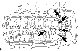 |
Install 5 new gaskets to the camshaft bearing caps. (No. 1, No. 3).
Install the cover gasket to the cylinder head cover.
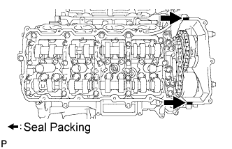 |
Apply seal packing as shown in the illustration.
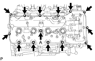 |
Install the cylinder head cover and a new seal washer with the 14 bolts.
| 6. INSTALL IGNITION COIL ASSEMBLY |
Install the 8 ignition coils with the 8 bolts.
| 7. CONNECT NO. 3 AIR TUBE |
Install a new gasket to the No. 3 air tube.
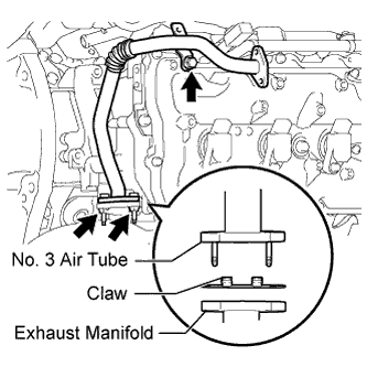 |
Connect the No. 3 air tube with the 2 nuts and bolt.
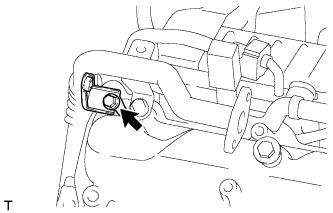 |
Install the wire harness clamp bracket with the bolt.
| 8. CONNECT NO. 4 AIR TUBE |
Install a new gasket to the No. 4 air tube.
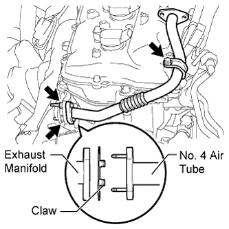 |
Connect the No. 4 air tube with the 2 nuts and bolt.
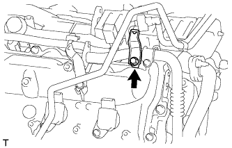 |
Install the wire harness clamp bracket with the bolt.
| 9. INSTALL CRANKSHAFT PULLEY |
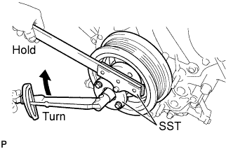 |
Align the key groove of the pulley with the pulley set key, and slide on the pulley to install it.
Using SST, install the pulley set bolt.
| 10. INSTALL NO. 1 IDLER PULLEY SUB-ASSEMBLY |
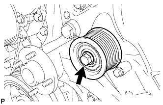 |
Install the idler pulley with the bolt.
| 11. INSTALL WATER PUMP PULLEY |
Temporarily install the pulley with the 4 bolts.
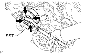 |
Using SST, hold the pulley and tighten the 4 bolts.
| 12. INSTALL FRONT WATER BY-PASS JOINT |
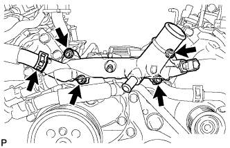 |
Install 2 new gaskets and the water by-pass joint with the 4 nuts.
Install the No. 2 water by-pass hose to the water by-pass joint.
| 13. INSTALL WATER INLET HOUSING |
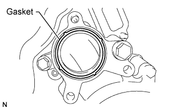 |
Install a new gasket to the timing chain cover.
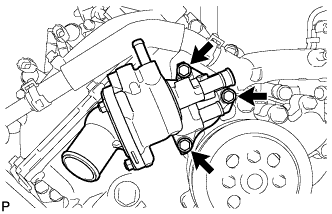 |
Install the water inlet housing with the 3 bolts.
| 14. CONNECT NO. 5 WATER BY-PASS HOSE |
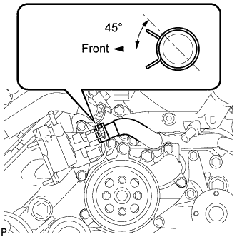 |
Connect the water by-pass hose.
| 15. CONNECT NO. 8 WATER BY-PASS HOSE |
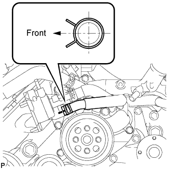 |
Connect the water by-pass hose.
| 16. INSTALL WATER BY-PASS PIPE SUB-ASSEMBLY |
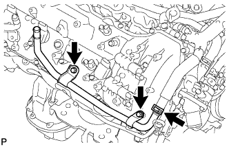 |
Connect the hose.
Install the water by-pass pipe with the 2 bolts.
| 17. INSTALL AIR TUBE SUB-ASSEMBLY RH |
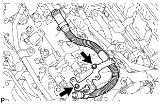 |
Install the air tube with the 2 bolts.
| 18. INSTALL NO. 1 WATER BY-PASS HOSE |
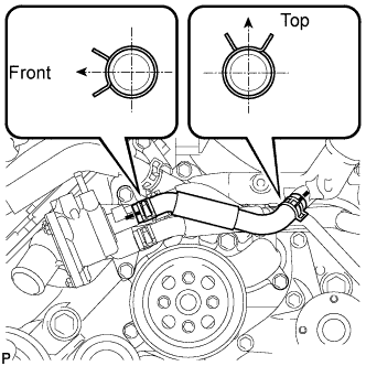 |
Install the water by-pass hose.
| 19. INSTALL NO. 3 ENGINE COVER |
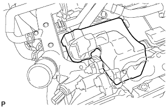 |
Install the No. 3 engine cover.
| 20. INSTALL NO. 4 ENGINE COVER |
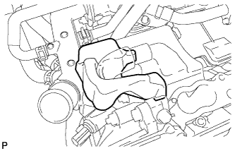 |
Install the No. 4 engine cover.
| 21. INSTALL GENERATOR ASSEMBLY |
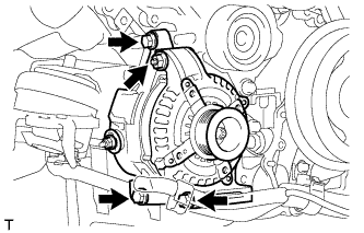 |
Install the generator with the 3 bolts and nut.
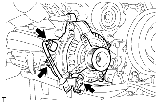 |
Install the harness bracket to the generator with the bolt.
Connect the generator connector.
Connect the generator wire with the nut.
Install the terminal cap.
| 22. CONNECT OIL COOLER TUBE SUB-ASSEMBLY (w/ Trailer Towing System) |
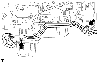 |
Connect the oil cooler tube with the 2 bolts.
| 23. CONNECT VANE PUMP ASSEMBLY |
 |
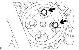 |
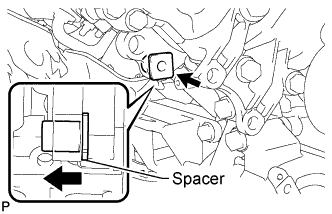
Connect the vane pump to the timing chain cover with the 2 bolts.
| 24. INSTALL ENGINE OIL LEVEL DIPSTICK GUIDE |
Apply a light coat of engine oil to a new O-ring.
Install the O-ring to the dipstick guide.
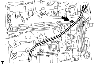 |
Install the dipstick guide with the bolt.
Install the dipstick.
| 25. INSTALL OIL FILTER BRACKET |
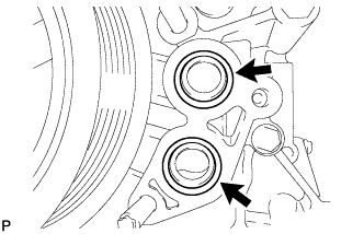 |
Apply a light coat of engine oil to 2 new O-rings.
Install the 2 O-rings to the timing chain cover.
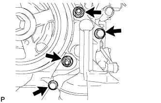 |
Install the oil filter bracket with the 2 nuts and 2 bolts.
| 26. INSTALL NO. 1 OIL COOLER BRACKET (w/ Oil Cooler) |
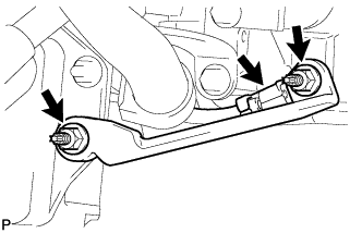 |
Connect the ground wire to the cylinder block.
Install the oil cooler bracket with the 2 nuts.
| 27. INSTALL WATER BY-PASS PIPE (w/ Oil Cooler) |
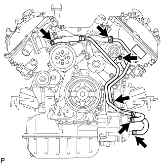 |
Connect the 4 hoses.
Install the water by-pass pipe with the 2 bolts.
| 28. INSTALL OIL PRESSURE SENDER GAUGE ASSEMBLY |
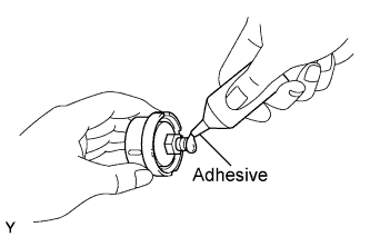 |
Apply adhesive to 2 or 3 threads of the oil pressure sender gauge.
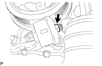 |
Install the oil pressure sender gauge.
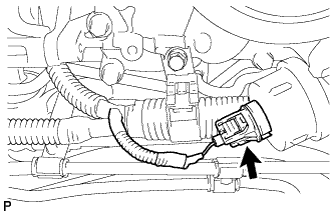 |
Connect the sender gauge connector.
| 29. INSTALL OIL FILTER ELEMENT |
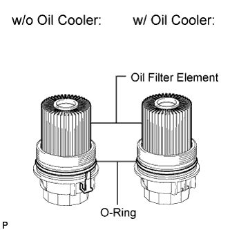 |
Clean the inside of the oil filter cap, its threads and its O-ring groove.
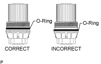 |
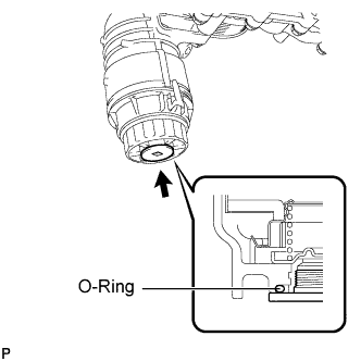
Apply a small amount of engine oil to a new O-ring and install it to the oil filter cap.
Set a new oil filter element to the oil filter cap.
Remove any dirt or foreign matter from the installation surface of the engine.
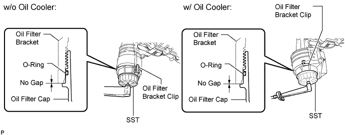
Apply a small amount of engine oil to the O-ring again and temporarily install the oil filter cap.
Using SST, tighten the oil filter cap.
 |
Apply a small amount of engine oil to a new drain plug O-ring, and install it to the oil filter cap.
Install the oil filter drain plug.
| 30. CONNECT COOLER COMPRESSOR ASSEMBLY |
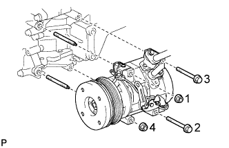 |
Connect the cooler compressor with the 2 stud bolts.
Install the 2 bolts and 2 nuts.
| 31. CONNECT HEATER HOSE AND NO. 1 WATER BY-PASS PIPE |
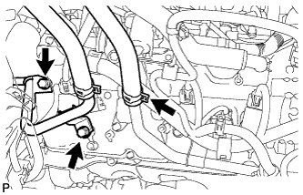 |
Connect the No. 1 water by-pass pipe with the 2 bolts.
Connect the heater hose.
| 32. CONNECT NO. 3 AIR INJECTION SYSTEM HOSE |
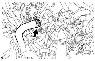 |
Connect the No. 3 air injection system hose.
| 33. CONNECT ENGINE WIRE |
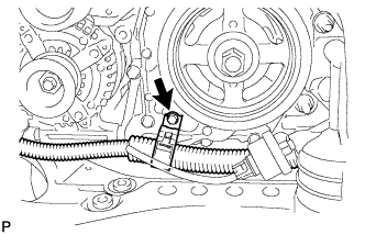 |
Connect the bracket to the timing chain cover with the bolt.
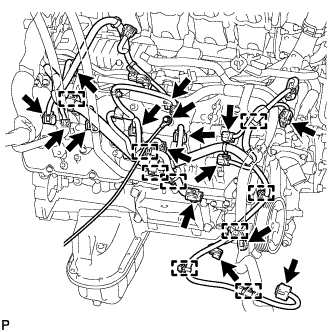 |
Engine Room RH Side:
Connect the 9 clamps.
Connect the 2 air pump connectors.
Install the ground wire with the bolt.
Connect the noise filter connector.
Connect the 2 VVT sensor connectors.
Connect the injector connector.
Connect the 4 ignition coil connectors.
Connect the 2 camshaft timing oil control valve connectors.
Connect the power steering oil pressure switch connector and solenoid valve connector.
for 4WD:
Connect the clamp and junction connector.
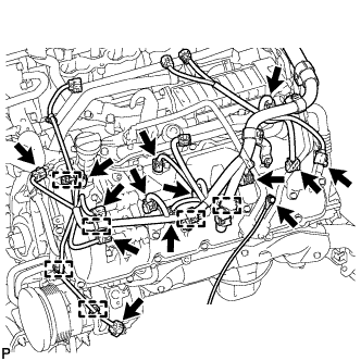 |
Engine Room LH Side:
Connect the cooler compressor connector.
Connect the 6 clamps.
Connect the camshaft position sensor connector.
Connect the 2 camshaft timing oil control valve connectors.
Connect the engine coolant temperature sensor connector.
Install the ground wire with the bolt.
Connect the noise filter connector.
Connect the 2 VVT sensor connectors.
Connect the 4 ignition coil connectors.
Connect the injector connector.
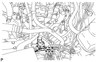 |
Connect the 2 wire harness clamps.
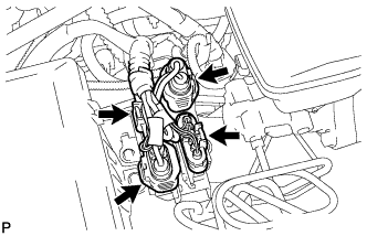 |
Connect the 4 air injection control driver connectors.
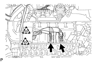 |
Connect the 2 connectors and attach the 2 clamps to the engine room junction block.
Install the engine room relay block cover.
| 34. INSTALL AIR SWITCHING VALVE ASSEMBLY (for Bank 2) |
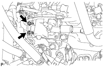
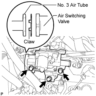 |
Install a new gasket and the air switching valve with the 3 bolts.
 |
Install the 2 bolts.
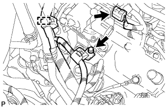 |
Connect the wire harness clamp bracket with the bolt.
Connect the clamp and connector.
| 35. CONNECT NO. 1 AIR HOSE |
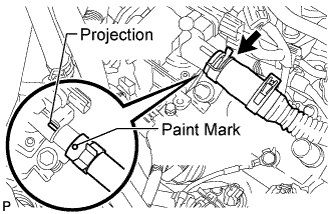 |
Align the paint mark with the projection and connect the No. 1 air hose.
| 36. INSTALL AIR SWITCHING VALVE ASSEMBLY (for Bank 1) |
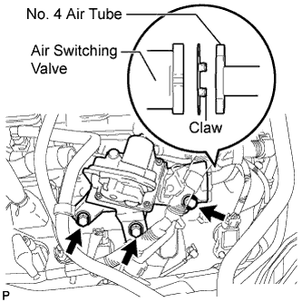 |
Install a new gasket and the air switching valve with the 3 bolts.
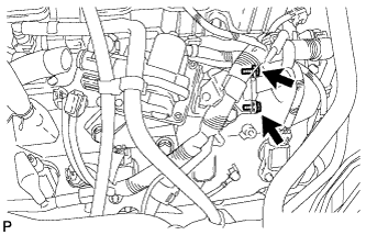 |
Install the 2 bolts.
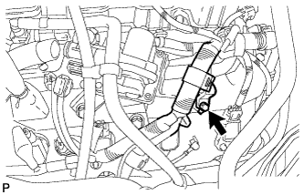 |
Connect the wire harness clamp bracket with the bolt.
| 37. INSTALL INTAKE MANIFOLD |
Install the intake manifold (Click here).
| 38. INSTALL RADIATOR ASSEMBLY |
Install the radiator (Click here).
| 39. ADD ENGINE OIL |
Add fresh oil.
| Oil Grade | Oil Viscosity (SAE) |
| ILSAC GF-5 multigrade engine oil | 0W-20 |
| Item | Specified Condition |
| Drain and refill without oil filter change | 7.1 liters (7.5 US qts, 6.2 Imp. qts) |
| Drain and refill with oil filter change | 7.5 liters (7.9 US qts, 6.6 Imp. qts) |
| Dry fill | 9.3 liters (9.8 US qts, 8.2 Imp. qts) |
Install the oil filler cap.
| 40. ADD ENGINE COOLANT |
Add engine coolant.
| Item | Specified Condition |
| w/ Trailer Towing System | 13.2 liters (13.9 US qts, 11.6 Imp. qts) |
| w/o Trailer Towing System | 12.1 liters (12.8 US qts, 10.6 Imp. qts) |
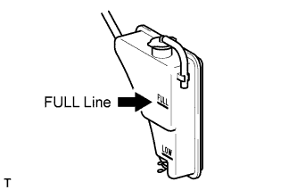 |
Slowly pour coolant into the radiator reservoir until it reaches the FULL line.
Install the reservoir cap.
Press the inlet and outlet radiator hoses several times by hand, and then check the coolant level. If the coolant level is low, add coolant.
Install the radiator cap.
Start the engine and warm it up until the thermostat opens.
Maintain the engine speed at 2000 to 2500 rpm.
Press the inlet and outlet radiator hoses several times by hand to bleed air.
Stop the engine, and wait until the engine coolant cools down to ambient temperature.
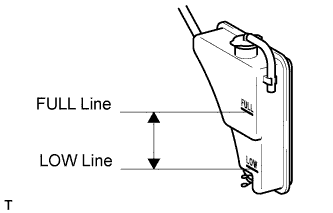 |
Check that the coolant level is between the FULL and LOW lines.
If the coolant level is below the LOW line, repeat all of the procedures above.
If the coolant level is above the FULL line, drain coolant so that the coolant level is between the FULL and LOW lines.
| 41. CONNECT CABLE TO NEGATIVE BATTERY TERMINAL |
| 42. INSPECT FOR OIL LEAK |
Start the engine. Make sure that there are no oil leaks from the area that was worked on.
| 43. INSPECT FOR COOLANT LEAK |
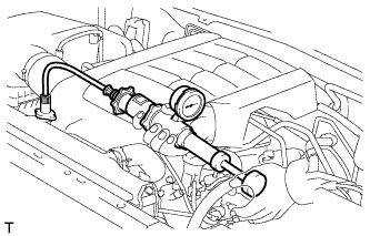 |
Fill the radiator with coolant and attach a radiator cap tester.
Warm up the engine.
Using the radiator cap tester, increase the pressure inside the radiator to 118 kPa (1.2 kgf/cm2, 17 psi), and check that the pressure does not drop.
If the pressure drops, check the hoses, radiator and water pump for leaks. If no external leaks are found, check the heater core, cylinder block and head.
| 44. CHECK ENGINE OIL LEVEL |
Warm up the engine, then stop the engine and wait for 5 minutes.
Check that the engine oil level is between the low level and full level marks on the dipstick.
If low, check for leakage and add oil up to the full level mark.