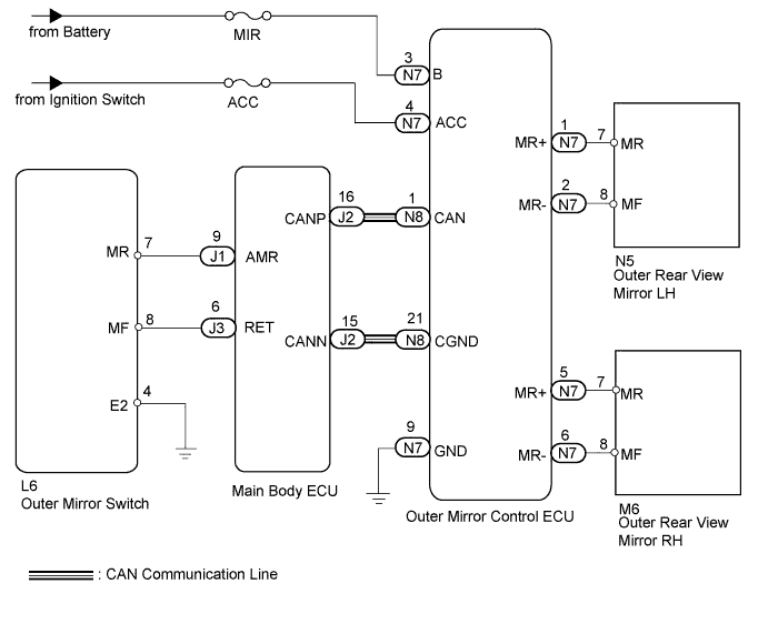
POWER MIRROR CONTROL SYSTEM (w/ Memory) > Power Retractable Mirrors do not Operate with Power Retract Mirror Switch |
| 1.CHECK DTC |
Use the Techstream to check if the CAN communication system is functioning normally (Click here).
| Result | Proceed to |
| CAN DTC is not output | A |
| CAN DTC is output | B |
|
| ||||
| A | |
 |
| 2.CHECK OUTER REAR VIEW MIRROR ASSEMBLY |
Operate the retract switch, and check that the outer rear view mirror operates.
| Result | Proceed to |
| Neither side operates | A |
| LH side does not operate | B |
| RH side does not operate | C |
|
| ||||
|
| ||||
| A | |
|
| 3.READ VALUE USING TECHSTREAM (MIRROR RETRACT SWITCH) |
Check the DATA LIST for proper functioning of the mirror retract switch.
| Tester Display | Measurement Item/Range | Normal Condition | Diagnostic Note |
| Outer Mirror Fold SW | Mirror retract switch signal / ON or OFF | ON: Switch is ON (retracting) OFF: Switch is OFF | - |
|
| ||||
| OK | |
|
| 4.CHECK HARNESS AND CONNECTOR (OUTER MIRROR CONTROL ECU - BATTERY, BODY GROUND) |
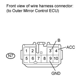 |
Disconnect the N7 ECU connector.
Measure the resistance according to the value(s) in the table below.
| Tester Connection | Condition | Specified Condition |
| N7-9 (GND) - Body ground | Always | Below 1 Ω |
Measure the voltage according to the value(s) in the table below.
| Tester Connection | Switch Condition | Specified Condition |
| N7-3 (B) - Body ground | Always | 11 to 14 V |
| N7-4 (ACC) - Body ground | Ignition switch LOCK | Below 1 V |
| Ignition switch ACC | 11 to 14 V |
|
| ||||
| OK | |
|
| 5.CHECK OUTER MIRROR CONTROL ECU (OPERATION) |
Temporarily replace the outer mirror control ECU with a normal one. (Click here)
Check that the outer rear view mirror operates normally.
|
| ||||
| OK | ||
 | ||
| ||
| 6.INSPECT OUTER REAR VIEW MIRROR LH |
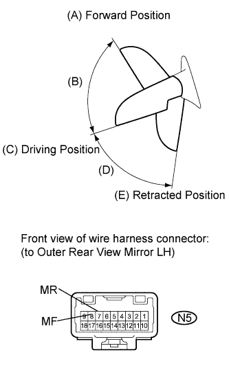 |
Remove the mirror LH (Click here).
For each mirror position: Disconnect the battery, set the mirror position by hand, connect the battery, and check the retractable mirror's movement.
| Measurement Condition | Mirror Position | Specified Condition |
| Battery positive (+) → Terminal 7 (MR) Battery negative (-) → Terminal 8 (MF) | Forward position (A) | Moves from (A) to retracted position (E) |
| Battery negative (-) → Terminal 7 (MR) Battery positive (+) → Terminal 8 (MF) | Forward position (A) | Does not move |
| Battery positive (+) → Terminal 7 (MR) Battery negative (-) → Terminal 8 (MF) | Position between forward position (A) and driving position (C) | Moves from (B) to retracted position (E) |
| Battery negative (-) → Terminal 7 (MR) Battery positive (+) → Terminal 8 (MF) | Position between forward position (A) and driving position (C) | Moves from (B) to forward position (A) |
| Battery positive (+) → Terminal 7 (MR) Battery negative (-) → Terminal 8 (MF) | Driving position (C) | Moves from (C) to retracted position (E) |
| Battery negative (-) → Terminal 7 (MR) Battery positive (+) → Terminal 8 (MF) | Driving position (C) | Does not move |
| Battery positive (+) → Terminal 7 (MR) Battery negative (-) → Terminal 8 (MF) | Position between driving position (C) and retracted position (E) | Moves from (D) to retracted position (E) |
| Battery negative (-) → Terminal 7 (MR) Battery positive (+) → Terminal 8 (MF) | Position between driving position (C) and retracted position (E) | Moves from (D) to driving position (C) |
| Battery positive (+) → Terminal 7 (MR) Battery negative (-) → Terminal 8 (MF) | Retracted position (E) | Does not move |
| Battery negative (-) → Terminal 7 (MR) Battery positive (+) → Terminal 8 (MF) | Retracted position (E) | Moves from (E) to driving position (C) |
|
| ||||
| OK | |
|
| 7.CHECK HARNESS AND CONNECTOR (OUTER REAR VIEW MIRROR LH - OUTER MIRROR CONTROL ECU) |
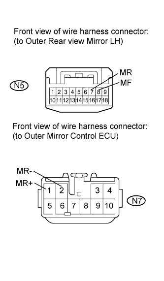 |
Disconnect the N7 ECU connector.
Disconnect the N5 mirror connector.
Measure the resistance according to the value(s) in the table below.
| Tester Connection | Condition | Specified Condition |
| N7-1 (MR+) - N5-7 (MR) | Always | Below 1 Ω |
| N7-2 (MR-) - N5-8 (MF) | ||
| N5-7 (MR) - Body ground | Always | 10 kΩ or higher |
| N5-8 (MF) - Body ground |
|
| ||||
| OK | ||
| ||
| ||
| 8.INSPECT OUTER REAR VIEW MIRROR RH |
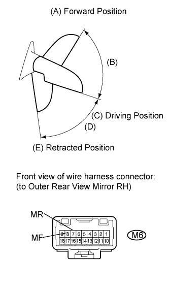 |
Remove the mirror RH (Click here).
For each mirror position: Disconnect the battery, set the mirror position by hand, connect the battery, and check the retractable mirror's movement.
| Measurement Condition | Mirror Position | Specified Condition |
| Battery positive (+) → Terminal 7 (MR) Battery negative (-) → Terminal 8 (MF) | Forward position (A) | Moves from (A) to retracted position (E) |
| Battery negative (-) → Terminal 7 (MR) Battery positive (+) → Terminal 8 (MF) | Forward position (A) | Does not move |
| Battery positive (+) → Terminal 7 (MR) Battery negative (-) → Terminal 8 (MF) | Position between forward position (A) and driving position (C) | Moves from (B) to retracted position (E) |
| Battery negative (-) → Terminal 7 (MR) Battery positive (+) → Terminal 8 (MF) | Position between forward position (A) and driving position (C) | Moves from (B) to forward position (A) |
| Battery positive (+) → Terminal 7 (MR) Battery negative (-) → Terminal 8 (MF) | Driving position (C) | Moves from (C) to retracted position (E) |
| Battery negative (-) → Terminal 7 (MR) Battery positive (+) → Terminal 8 (MF) | Driving position (C) | Does not move |
| Battery positive (+) → Terminal 7 (MR) Battery negative (-) → Terminal 8 (MF) | Position between driving position (C) and retracted position (E) | Moves from (D) to retracted position (E) |
| Battery negative (-) → Terminal 7 (MR) Battery positive (+) → Terminal 8 (MF) | Position between driving position (C) and retracted position (E) | Moves from (D) to driving position (C) |
| Battery positive (+) → Terminal 7 (MR) Battery negative (-) → Terminal 8 (MF) | Retracted position (E) | Does not move |
| Battery negative (-) → Terminal 7 (MR) Battery positive (+) → Terminal 8 (MF) | Retracted position (E) | Moves from (E) to driving position (C) |
|
| ||||
| OK | |
|
| 9.CHECK HARNESS AND CONNECTOR (OUTER REAR VIEW MIRROR RH - OUTER MIRROR CONTROL ECU) |
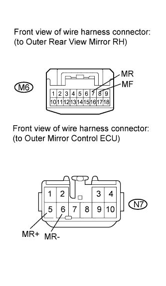 |
Disconnect the N7 ECU connector.
Disconnect the M6 mirror connector.
Measure the resistance according to the value(s) in the table below.
| Tester Connection | Condition | Specified Condition |
| N7-5 (MR+) - M6-7 (MR) | Always | Below 1 Ω |
| N7-6 (MR-) - M6-8 (MF) | ||
| M6-7 (MR) - Body ground | Always | 10 kΩ or higher |
| M6-8 (MF) - Body ground |
|
| ||||
| OK | ||
| ||
| ||
| 10.INSPECT OUTER MIRROR SWITCH |
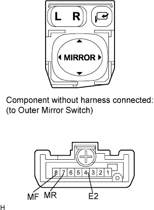 |
Remove the switch (Click here).
Measure the resistance according to the value(s) in the table below.
| Tester Connection | Switch Condition | Specified Condition |
| 4 (E2) - 7 (MR) | Pressed (Retracts) | 10 kΩ or higher |
| Not pressed | Below 1 Ω | |
| 4 (E2) - 8 (MF) | Pressed (Returns) | Below 1 Ω |
| Not pressed | 10 kΩ or higher |
|
| ||||
| OK | |
|
| 11.CHECK HARNESS AND CONNECTOR (OUTER MIRROR SWITCH - MAIN BODY ECU AND BODY GROUND) |
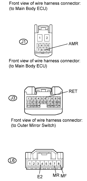 |
Disconnect the J1 and J3 ECU connectors.
Disconnect the L6 switch connector.
Measure the resistance according to the value(s) in the table below.
| Tester Connection | Condition | Specified Condition |
| J1-9 (AMR) - L6-7 (MR) | Always | Below 1 Ω |
| J3-6 (RET) - L6-8 (MF) | ||
| L6-4 (E2) - Body ground | ||
| L6-7 (MR) - Body ground | Always | 10 kΩ or higher |
| L6-8 (MF) - Body ground |
|
| ||||
| OK | ||
| ||
| ||

