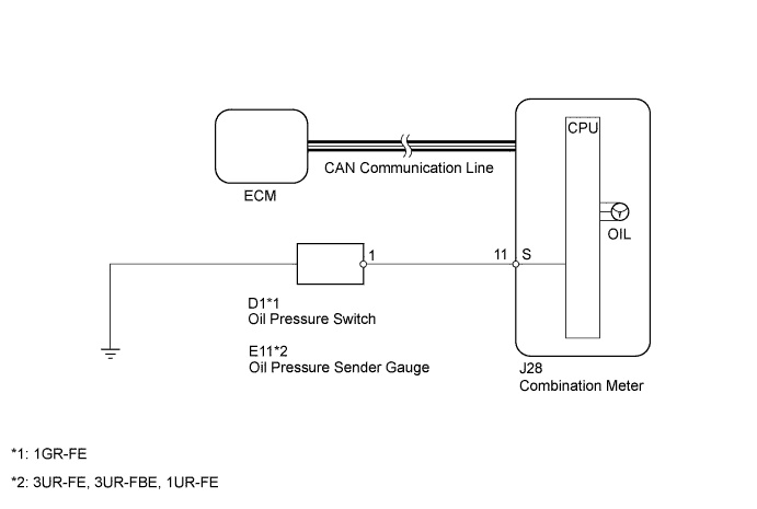
METER / GAUGE SYSTEM > Oil Pressure Gauge Malfunction |
| 1.CHECK CAN COMMUNICATION SYSTEM |
Check for DTCs (Click here).
| Result | Proceed to |
| CAN communication system DTC is not output | A |
| CAN communication system DTC is output | B |
|
| ||||
| A | |
 |
| 2.PERFORM ACTIVE TEST USING TECHSTREAM (OIL PRESSURE RECEIVER GAUGE) |
Operate the Techstream according to the display and select or "Active Test" (Click here).
| Tester Display | Test Part | Control Range | Diagnostic Note |
| Oil Pressure Meter Operation | Oil pressure receiver gauge | LOW, 1/4, 1/2, 3/4 or HIGH | Perform the test with the vehicle stopped and engine idling |
| Result | Proceed to |
| OK (for 1GR-FE) | A |
| OK (for 1UR-FE, 3UR-FE, 3UR-FBE) | B |
| NG | C |
|
| ||||
|
| ||||
| A | |
|
| 3.INSPECT OIL PRESSURE SWITCH |
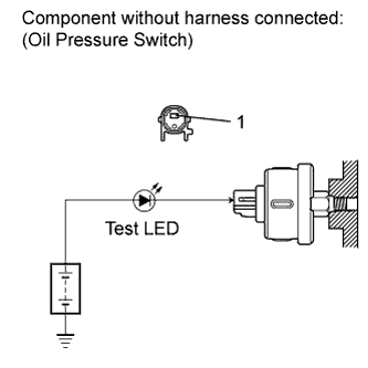 |
Disconnect the D1 switch connector.
Apply battery positive (+) voltage to the pressure switch terminal through a test LED.
Check that the LED does not illuminate when the engine is stopped.
Check that the LED flashes when the engine is running. The number of flashes varies with engine speed.
|
| ||||
| OK | |
|
| 4.CHECK HARNESS AND CONNECTOR (COMBINATION METER - OIL PRESSURE SWITCH) |
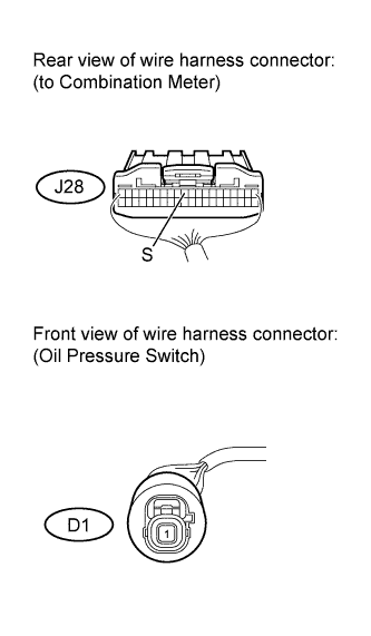 |
Disconnect the J28 meter connector.
Disconnect the D1 switch connector.
Measure the resistance according to the value(s) in the table below.
| Tester Connection | Condition | Specified Condition |
| J28-11 (S) - D1-1 | Always | Below 1 Ω |
| J28-11 (S) or D1-1 - Body ground | Always | 10 kΩ or higher |
|
| ||||
| OK | ||
 | ||
| ||
| 5.INSPECT OIL PRESSURE SENDER GAUGE |
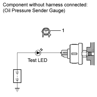 |
Disconnect the E11 sender gauge connector.
Apply battery positive (+) voltage to the sender gauge terminal through a test LED.
Check that the LED does not illuminate when the engine is stopped.
Check that the LED flashes when the engine is running. The number of flashes varies with engine speed.
| Result | Proceed to |
| LED operates correctly according to engine condition | A |
| LED does not operate correctly according to engine condition (for 1UR-FE) | B |
| LED does not operate correctly according to engine condition (for 3UR-FE) | C |
| LED does not operate correctly according to engine condition (for 3UR-FBE) | D |
|
| ||||
|
| ||||
|
| ||||
| A | |
|
| 6.CHECK HARNESS AND CONNECTOR |
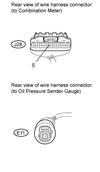 |
Disconnect the J28 meter connector.
Disconnect the E11 gauge connector.
Measure the resistance according to the value(s) in the table below.
| Tester Connection | Condition | Specified Condition |
| J28-11 (S) - E11-1 | Always | Below 1 Ω |
| J28-11 (S) or E11-1 - Body ground | Always | 10 kΩ or higher |
|
| ||||
| OK | ||
| ||
| ||

