 |
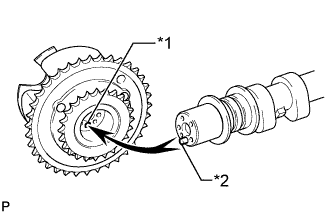
Put the camshaft timing gear assembly and camshaft together by aligning the pin hole and straight pin.
| *1 | Pin Hole |
| *2 | Straight Pin |
CAMSHAFT > INSTALLATION |
| 1. INSTALL CAMSHAFT TIMING GEAR ASSEMBLY |
Fix the camshaft in place.
|
Put the camshaft timing gear assembly and camshaft together by aligning the pin hole and straight pin.
| *1 | Pin Hole |
| *2 | Straight Pin |
Lightly press and turn the camshaft timing gear assembly against the camshaft, and press harder after the pin enters the hole.
Check that there is no clearance between the camshaft timing gear assembly flange and camshaft.
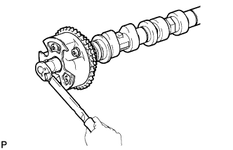 |
Install the flange bolt while holding the camshaft.
Check the lock of the camshaft timing gear assembly.
Fix the camshaft in place and confirm that the camshaft timing gear assembly is locked.
| 2. INSTALL CAMSHAFT TIMING EXHAUST GEAR ASSEMBLY |
Fix the camshaft in place.
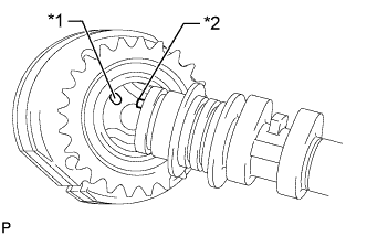 |
Put the camshaft timing exhaust gear assembly and camshaft together by aligning the pin hole and straight pin.
| *1 | Pin Hole |
| *2 | Straight Pin |
Lightly press and turn the camshaft timing gear assembly against the camshaft, and press harder after the pin enters the hole.
Check that there is no clearance between the gear flange and camshaft.
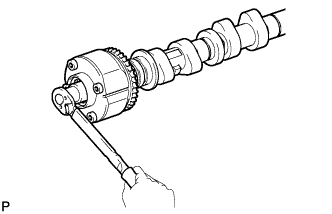 |
Install the flange bolt while holding the camshaft.
Check the camshaft timing exhaust gear lock.
Make sure that the camshaft timing exhaust gear assembly locks.
| 3. INSTALL NO. 3 CAMSHAFT |
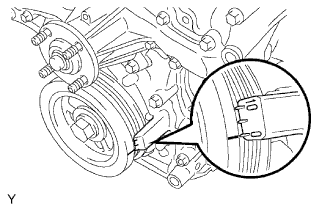 |
Check that the notch is aligned with the "0" timing mark of the timing chain cover.
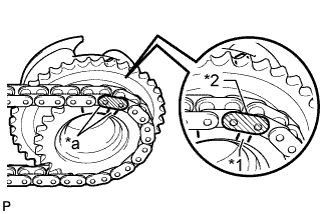 |
Align the mark plate (yellow) with the timing mark of the camshaft timing gear as shown in the illustration and install the No. 2 chain to the camshaft timing gear.
| *1 | Timing Mark |
| *2 | Mark Plate (yellow) |
| *a | Align |
Clean the camshaft housing LH and camshaft journals and apply engine oil to them.
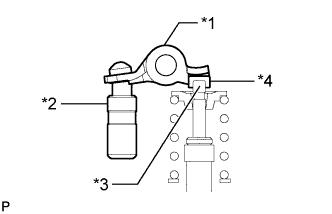 |
Make sure that the No. 1 valve rocker arm sub-assembly is installed as shown in the illustration.
| *1 | Valve Rocker Arm |
| *2 | Lash Adjuster |
| *3 | Valve Stem |
| *4 | Valve Stem Cap |
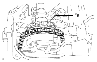 |
Install the chain to the No. 3 camshaft, and then install the camshaft to the camshaft housing LH.
| *a | Place on camshaft timing gear |
| 4. INSTALL NO. 4 CAMSHAFT |
Clean the camshaft housing LH and camshaft journals and apply engine oil to them.
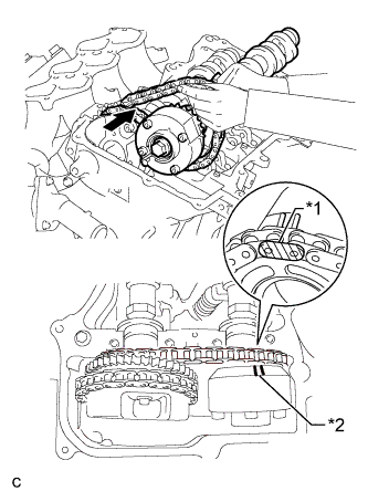 |
Pass the No. 4 camshaft through the No. 2 chain from the front of the vehicle, align the mark plate (yellow) with the timing mark and install the No. 2 chain to the camshaft timing exhaust gear.
| *1 | Mark Plate (yellow) |
| *2 | Timing Mark |
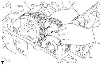 |
While lifting up the No. 4 camshaft, pass the No. 3 chain tensioner assembly through the No. 2 chain and set it in place.
Install the No. 4 camshaft to the camshaft housing LH, and then install the No. 3 chain tensioner assembly with the bolt.
| 5. INSTALL CAMSHAFT BEARING CAP (for Bank 2) |
Clean the camshaft bearing caps and apply engine oil to them.
|
Make sure that the No. 1 valve rocker arm sub-assembly is installed as shown in the illustration.
| *1 | Valve Rocker Arm |
| *2 | Lash Adjuster |
| *3 | Valve Stem |
| *4 | Valve Stem Cap |
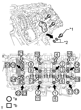 |
Check the marks and numbers on the camshaft bearing caps, and then remove the replacement bolts and washers in the order shown in the illustration. Immediately after removing the bolts and washers for temporary installation of the camshaft housing in the location for a bearing cap, install the bearing cap with the bolts in the order shown in the illustration.
| *1 | Bolt |
| *2 | Washer |
| *a | Installation of Bolts and Washers for Temporary Installation of camshaft housing |
| *b | Part Installation |
 | Bolt A |
 | Bolt B |
Check the torque of each bolt again.
| 6. CONNECT CHAIN SUB-ASSEMBLY (for Bank 2) |
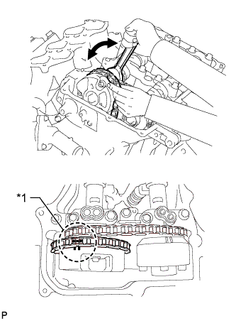 |
Align the paint marks on the camshaft timing gear and No. 1 chain and install the No. 1 chain to the camshaft timing gear.
| *1 | Paint Mark |
| 7. INSTALL CAMSHAFT |
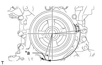 |
Turn the crankshaft clockwise until it is in the position shown in the illustration so that the chain can be installed easily.
| *a | 5° to 10° |
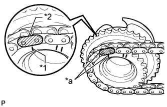 |
Align the mark plate (yellow) with the timing mark of the camshaft timing gear as shown in the illustration and install the No. 2 chain to the camshaft timing gear.
| *1 | Timing Mark |
| *2 | Mark Plate (yellow) |
| *a | Align |
Clean the camshaft housing RH and camshaft journals and apply engine oil to them.
|
Make sure that the No. 1 valve rocker arm sub-assembly is installed as shown in the illustration.
| *1 | Valve Rocker Arm |
| *2 | Lash Adjuster |
| *3 | Valve Stem |
| *4 | Valve Stem Cap |
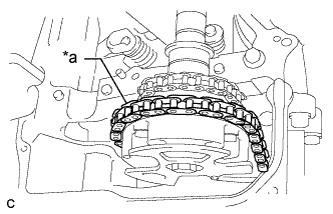 |
Install the chain to the camshaft, and then install the camshaft to the camshaft housing RH.
| *a | Place on camshaft timing gear |
| 8. INSTALL NO. 2 CAMSHAFT |
Clean the camshaft housing RH and camshaft journals and apply engine oil to them.
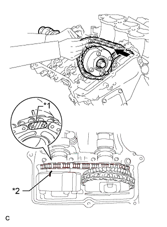 |
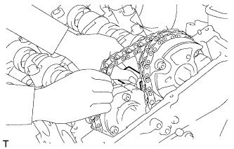
Pass the No. 2 camshaft through the No. 2 chain from the front of the vehicle, align the mark plate (yellow) with the timing mark and install the No. 2 chain to the camshaft timing exhaust gear.
| *1 | Mark Plate (yellow) |
| *2 | Timing Mark |
 |
While lifting up the No. 2 camshaft, pass the No. 2 chain tensioner assembly through the No. 2 chain and set it in place.
Install the No. 2 camshaft to the camshaft housing RH, and then install the No. 2 chain tensioner assembly with the bolt.
| 9. INSTALL CAMSHAFT BEARING CAP (for Bank 1) |
Clean the camshaft bearing caps and apply engine oil to them.
|
Make sure that the No. 1 valve rocker arm sub-assembly is installed as shown in the illustration.
| *1 | Valve Rocker Arm |
| *2 | Lash Adjuster |
| *3 | Valve Stem |
| *4 | Valve Stem Cap |
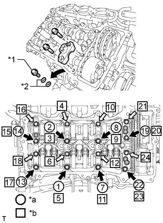 |
Check the marks and numbers on the camshaft bearing caps, and then remove the replacement bolts and washers in the order shown in the illustration. Immediately after removing the bolts and washers for temporary installation of the camshaft housing in the location for a bearing cap, install the bearing cap with the bolts in the order shown in the illustration.
| *1 | Bolt |
| *2 | Washer |
| *a | Installation of Bolts and Washers for Temporary Installation of camshaft housing |
| *b | Part Installation |
| Bolt A |
| Bolt B |
Check the torque of each bolt again.
| 10. CONNECT CHAIN SUB-ASSEMBLY (for Bank 1) |
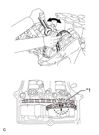 |
Align the paint marks on the camshaft timing gear and No. 1 chain and install the No. 1 chain to the camshaft timing gear.
| *1 | Paint Mark |
| 11. INSTALL NO. 1 CHAIN TENSIONER ASSEMBLY |
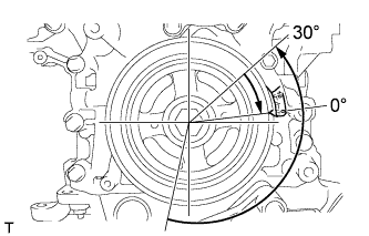 |
Turn the crankshaft counterclockwise 30° past the "0" timing mark, and then turn it clockwise to align the notch with the "0" timing mark.
Turn the crankshaft slightly to eliminate the slack in the chain.
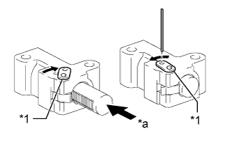 |
While turning the stopper plate of the tensioner clockwise, push in the plunger of the tensioner as shown in the illustration.
| *1 | Stopper Plate |
| *a | Push |
While turning the stopper plate of the tensioner counterclockwise, insert a pin of 1.27 mm (0.0500 in.) into the holes in the stopper plate and tensioner to fix the stopper plate in place.
Install the chain tensioner with the 2 bolts.
Remove the pin from the No. 1 chain tensioner.
| 12. INSPECT VALVE TIMING |
Check the camshaft timing marks.
Check that each camshaft timing mark is positioned as shown in the illustration.
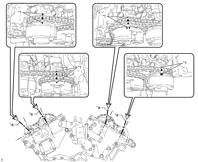
| *1 | Timing Mark | - | - |
| *a | Viewpoint | - | - |
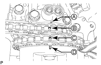 |
If the valve timing is misaligned, reinstall the timing chain.
Turn the crankshaft 2 revolutions, set the No. 1 cylinder to TDC/compression and check the timing marks again.
| 13. INSTALL TIMING CHAIN COVER PLATE |
Install a new gasket and the timing chain cover plate with the 4 bolts.
| 14. POUR ENGINE OIL |
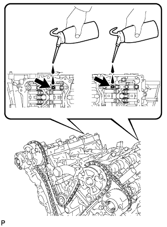 |
| 15. INSTALL CYLINDER HEAD COVER SUB-ASSEMBLY |
Remove any old packing (FIPG material) and be careful not to drop any oil on the contact surfaces of the cylinder head, timing chain cover and cylinder head cover.
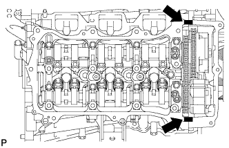 |
Apply seal packing as shown in the illustration.
| Seal Packing |
Install 3 new gaskets.
Install a new gasket to the cylinder head cover.
Install the seal washers to the bolts.
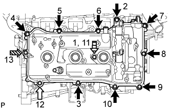 |
Temporarily install the cylinder head cover with the 12 bolts. Tighten the bolts uniformly in several steps.
| Item | Length |
| A | 25 mm (0.984 in.) |
| B | 35 mm (1.38 in.) |
| C | 65 mm (2.56 in.) |
| D | 60 mm (2.36 in.) |
| Bolt A |
| Bolt B |
 | Bolt C |
 | Bolt D |
| 16. INSTALL CYLINDER HEAD COVER SUB-ASSEMBLY LH |
Remove any old packing (FIPG material) and be careful not to drop any oil on the contact surfaces of the cylinder head, timing chain cover and cylinder head cover.
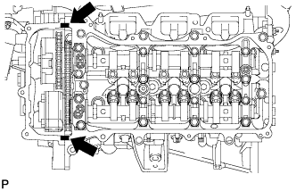 |
Apply seal packing as shown in the illustration.
| Seal Packing |
Install 3 new gaskets.
Install a new gasket to the cylinder head cover.
Install the seal washers to the bolts.
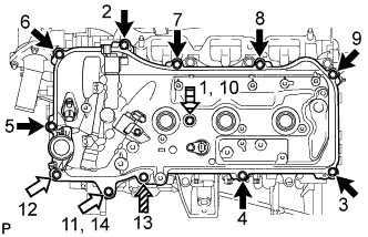 |
Temporarily install the cylinder head cover with the 12 bolts. Tighten the bolts uniformly in several steps.
| Item | Length |
| A | 25 mm (0.984 in.) |
| B | 35 mm (1.38 in.) |
| C | 70 mm (2.76 in.) |
| D | 60 mm (2.36 in.) |
| Bolt A |
| Bolt B |
| Bolt C |
| Bolt D |
| 17. CONNECT FUEL PIPE SUB-ASSEMBLY |
Connect the fuel pipe with the 2 bolts.
| 18. INSTALL NO. 2 OIL PIPE |
Make sure that there is no foreign matter on the mesh of the oil control valve filter RH.
Install a new gasket and temporarily install the oil pipe (on the cylinder head side) with the oil check valve bolt.
Install the oil control valve filter RH to the oil pipe union. Install new gaskets and temporarily install the oil pipe (on the head cover side).
Tighten the oil pipe union (on the cylinder head side).
Tighten the oil pipe union (on the head cover side).
| 19. INSTALL NO. 1 OIL PIPE |
Make sure that there is no foreign matter on the mesh of the oil control valve filter LH.
Install a new gasket and temporarily install the oil pipe (on the cylinder head side) with the oil check valve bolt.
Install the oil control valve filter LH to the oil pipe union. Install new gaskets and temporarily install the oil pipe (on the head cover side).
Tighten the oil pipe union (on the cylinder head side).
Tighten the oil pipe union (on the head cover side).
| 20. INSTALL WATER BY-PASS PIPE SUB-ASSEMBLY |
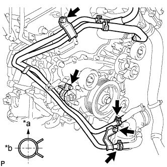 |
Install the water by-pass pipe with the 3 bolts.
Connect the 2 hoses.
| *a | Upward |
| *b | Rearward |
| 21. INSTALL ENGINE OIL LEVEL DIPSTICK GUIDE |
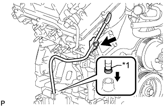 |
Install a new O-ring to the dipstick guide.
| *1 | New O-Ring |
Apply a light coat of engine oil to the O-ring.
Push the dipstick guide end into the guide hole.
Install the dipstick guide with the bolt.
Install the dipstick.
| 22. INSTALL GENERATOR ASSEMBLY |
Install the generator bracket to the generator with the bolt.
Install the generator with the 2 bolts.
Install the generator bracket with the bolt.
Attach the wire harness clamp.
Connect the wire harness bracket with the bolt.
Connect the generator connector to the generator.
Install the generator wire with the nut.
Close the terminal cap.
| 23. INSTALL NO. 2 EXHAUST MANIFOLD HEAT INSULATOR |
Install the heat insulator with the 3 bolts.
| 24. INSTALL NO. 2 IDLER PULLEY SUB-ASSEMBLY |
for Separate Type:
Install the 2 idler pulley cover plates, 2 No. 2 idler pulleys and 2 No. 2 idler pulley cover plates with the 2 bolts.
for Integrated Type:
Install the 2 No. 2 idler pulleys with the 2 bolts.
| 25. CONNECT HEATER WATER PIPE SUB-ASSEMBLY |
Connect the water by-pass pipe with the 2 bolts.
| 26. CONNECT WIRE HARNESS |
Attach the 3 wire harness clamps.
Connect the engine coolant temperature sensor connector.
| 27. CONNECT VANE PUMP ASSEMBLY |
Connect the vane pump with the 2 bolts.
Attach the wire harness clamp.
Connect the connector.
| 28. INSTALL IGNITION COIL ASSEMBLY |
Install the 6 ignition coils with the 6 bolts.
Connect the 6 ignition coil connectors.
| 29. INSTALL NO. 2 EMISSION CONTROL VALVE SET |
Install the No. 2 emission control valve set with the 3 nuts.
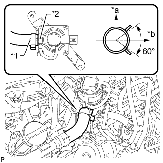 |
Align the paint mark with the projection and connect the air hose.
| *1 | Paint Mark |
| *2 | Projection |
| *a | Top |
| *b | LH Side |
Connect the No. 2 emission control valve set connector.
| 30. INSTALL EMISSION CONTROL VALVE SET |
Install the emission control valve set with the 3 nuts.
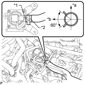 |
Align the paint mark with the projection and connect the air hose.
| *1 | Projection |
| *2 | Paint Mark |
| *a | Upper |
| *b | RH Side |
Connect the emission control valve set connector.
| 31. INSTALL NO. 2 AIR TUBE |
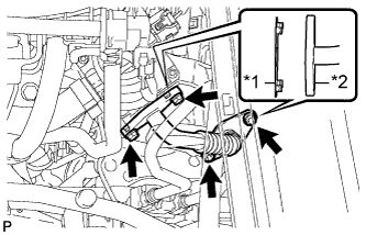 |
Install 2 new gaskets to the No. 2 air tube as shown in the illustration.
| *1 | New Gasket |
| *2 | No. 2 Air Tube |
Install the No. 2 air tube with the 2 bolts and 2 nuts.
| 32. INSTALL AIR TUBE |
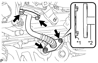 |
Install 2 new gaskets to the air tube as shown in the illustration.
| *1 | New Gasket |
| *2 | Air Tube |
Install the air tube with the 2 bolts and 2 nuts.
| 33. INSTALL INTAKE AIR SURGE TANK |
Install a new gasket to the intake air surge tank.
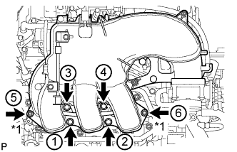 |
Install the intake air surge tank with the 4 bolts and 2 nuts in the order shown in the illustration.
| *1 | Nut |
Install the throttle body bracket with the 2 bolts.
Install the No. 1 surge tank stay with the 2 bolts.
Attach the wire harness clamp.
Install the No. 2 surge tank stay with the 2 bolts.
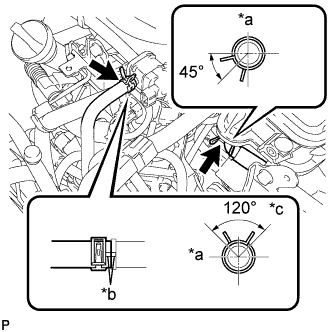 |
Connect the No. 1 ventilation hose.
Connect the vacuum hose.
Connect the No. 1 fuel feed hose.
| *a | Front |
| *b | Matchmark |
| *c | Top |
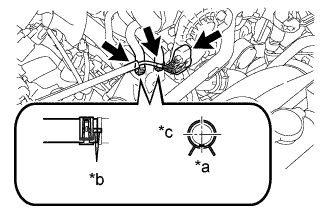 |
Connect the throttle body connector.
Connect the No. 4 water by-pass hose.
Connect the No. 5 water by-pass hose.
Connect the 2 heater hose clamps.
| *a | Front |
| *b | Matchmark |
| *c | RH |
| 34. INSTALL AIR TUBE ASSEMBLY |
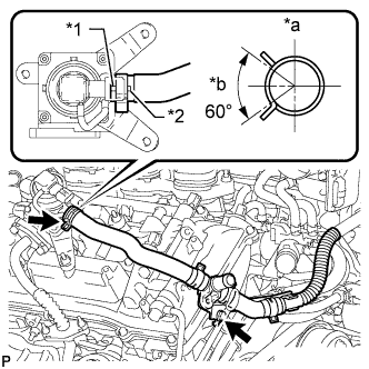 |
for Bank 1 Side:
Align the paint mark with the projection and connect the air tube assembly to the emission control valve set.
| *1 | Projection |
| *2 | Paint Mark |
| *a | Upper |
| *b | RH Side |
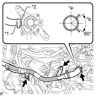 |
for Bank 2 Side:
Align the paint mark with the projection and connect the air tube assembly to the No. 2 emission control valve set.
| *1 | Paint Mark |
| *2 | Projection |
| *a | Upper |
| *b | LH Side |
Install the 3 bolts.
Install the wire harness clamp bracket with the bolt.
Attach the 3 wire harness clamps to the intake air surge tank and bracket.
Connect the purge VSV connector.
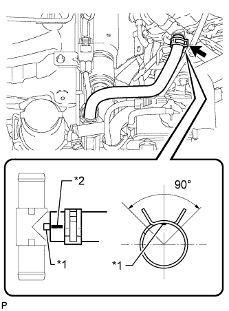 |
Connect the air injection system hose to the air tube assembly shown in the illustration.
| *1 | Paint Mark |
| *2 | Projection |
| *a | Upper |
| *b | LH Side |
| 35. INSTALL FAN SHROUD |
Install the fan pulley to the water pump.
Place the shroud together with the coupling fan between the radiator and engine.
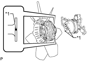 |
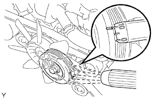
Align the paint marks on the heads of the water pump stud bolts with the paint marks of the same color on the outer edge of the fluid coupling flange and install the fluid coupling to the water pump.
| *1 | Paint Mark |
Temporarily install the fluid coupling fan to the water pump with the 4 nuts. Tighten the nuts as much as possible by hand.
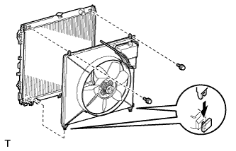 |
Attach the claws of the shroud to the radiator as shown in the illustration.
Install the shroud with the 2 bolts.
Connect the reservoir hose to the radiator tank upper.
Install the fan and generator V-belt .
Tighten the 4 nuts of the fluid coupling fan.
| 36. INSTALL RADIATOR HOSE OUTLET |
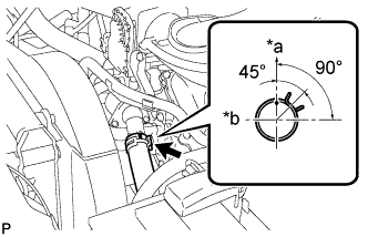 |
Connect the radiator hose outlet to the water inlet housing shown in the illustration.
| *a | Upper |
| *b | Front |
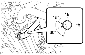 |
Install the radiator hose outlet to the radiator shown in the illustration.
| *a | Upper |
| *b | RH |
| 37. INSTALL RADIATOR HOSE INLET |
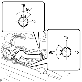 |
Connect the radiator hose inlet as shown in the illustration.
| *a | Upper |
| *b | LH |
| *c | Front |
| 38. INSTALL AIR CLEANER CAP AND HOSE |
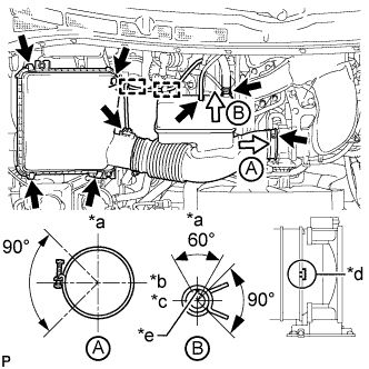 |
Install the air cleaner cap and hose.
| *a | Top |
| *b | Front |
| *c | RH Side |
| *d | Align cutout portion of hose with protrusion of throttle |
| *e | Paint Mark |
Attach the 4 hook clamps to install the air cleaner cap and hose.
Tighten the clamp.
Attach the 4 clamps and connect the ventilation hose, vacuum hose and mass air flow meter connector.
| 39. CONNECT CABLE TO POSITIVE BATTERY TERMINAL |
| 40. CONNECT CABLE TO NEGATIVE BATTERY TERMINAL |
| 41. ADD ENGINE COOLANT |
Add engine coolant.
Slowly pour coolant into the radiator reservoir until it reaches the FULL line.
Install the reservoir cap.
Install the radiator cap.*1
Start the engine and stop it immediately.*2
Allow approximately 10 seconds to pass. Then remove the radiator cap and check the coolant level. If the coolant level has decreased, add coolant.*3
Repeat steps *1, *2 and *3 until the coolant level does not decrease.
Install the radiator cap.*4
Set the air conditioning as follows.*5
| Item | Condition |
| Fan speed | Any setting except off |
| Temperature | Toward WARM |
| Air conditioning switch | Off |
Start the engine, warm it up until the thermostat opens, and then continue to run the engine for several minutes to circulate the coolant.*6
Stop the engine, wait until the engine coolant cools down to ambient temperature. Then remove the radiator cap and check the coolant level.*7
If the coolant level has decreased, add coolant and warm up the engine until the thermostat opens.*8
If the coolant level has not decreased, check that the coolant level in the radiator reservoir is at the FULL line.
If the coolant level is below the FULL line, repeat steps *4 through *8.
If the coolant level is above the FULL line, drain coolant until the coolant level reaches the FULL line.
| 42. ADD ENGINE OIL |
Add fresh oil.
| Oil grade | Oil Viscosity (SAE) |
| ILSAC GF-5 multigrade engine oil | 0W-20 |
| Item | Specified Condition |
| Drain and refill without oil filter change | 5.6 liters (5.9 US qts, 4.9 Imp. qts) |
| Drain and refill with oil filter change | 6.1 liters (6.4 US qts, 5.4 Imp. qts) |
| Dry fill | 7.0 liters (7.4 US qts, 6.2 Imp. qts) |
| 43. INSPECT FOR COOLANT LEAK |
Fill the radiator with coolant and attach a radiator cap tester.
Warm up the engine.
Using the radiator cap tester, increase the pressure inside the radiator to 118 kPa (1.2 kgf/cm2, 17 psi), and check that the pressure does not drop.
If the pressure drops, check the hoses, radiator and water pump for leaks. If no external leaks are found, check the heater core, cylinder block and head.
| 44. INSPECT FOR ENGINE OIL LEAK |
Start the engine. Make sure that there are no oil leaks from the area that was worked on.
| 45. INSTALL NO. 1 ENGINE UNDER COVER |
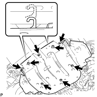 |
Hook the engine under cover to the vehicle body as shown in the illustration.
Install the 3 screws and 5 bolts.
| 46. INSPECT IGNITION TIMING |
Warm up the engine.
When using the Techstream:
Connect the Techstream to the DLC3.
Enter the following menus: Powertrain / Engine and ECT / Data List / All Data / IGN Advance.
Inspect the ignition timing during idling.
Check that the ignition timing advances immediately when the engine speed is increased.
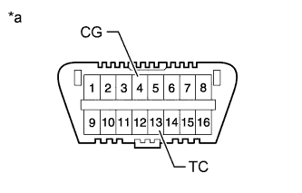 |
When not using the Techstream:
Using SST, connect terminals 13 (TC) and 4 (CG) of the DLC3.
| *a | Front view of DLC3 |
Connect the tester probe of a timing light to the wire of the ignition coil connector for the No. 1 cylinder.
 |
Inspect the ignition timing during idling.
Remove SST from the DLC3.
Inspect the ignition timing during idling.
Disconnect the timing light from the engine.