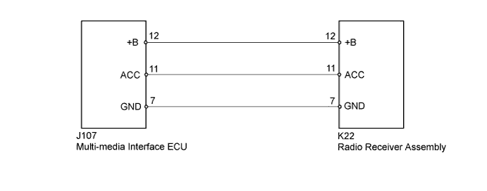
AUDIO AND VISUAL SYSTEM > Multi-media Interface ECU Power Source Circuit |
| 1.CHECK MULTI-MEDIA INTERFACE ECU |
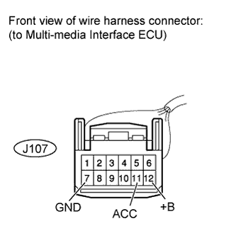 |
Disconnect the J107 multi-media interface ECU connector.
Measure the voltage according to the value(s) in the table below.
| Tester Connection | Switch Condition | Specified Condition |
| J107-12 (+B) - J107-7 (GND) | Always | 11 to 14 V |
| J107-11 (ACC) - J107-7 (GND) | Ignition switch ACC | 11 to 14 V |
|
| ||||
| OK | ||
 | ||
| ||
| 2.CHECK HARNESS AND CONNECTOR (MULTI-MEDIA INTERFACE ECU - RADIO RECEIVER) |
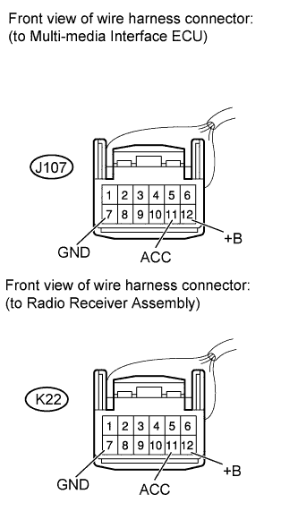 |
Disconnect the J107 multi-media interface ECU connector.
Disconnect the K22 radio receiver assembly connector.
Measure the resistance according to the value(s) in the table below.
| Tester Connection | Condition | Specified Condition |
| J107-11 (ACC) - K22-11 (ACC) | Always | Below 1 Ω |
| J107-12 (+B) - K22-12 (+B) | Always | Below 1 Ω |
| J107-7 (GND) - K22-7 (GND) | Always | Below 1 Ω |
| J107-11 (ACC) - Body ground | Always | 10 kΩ or higher |
| J107-12 (B+) - Body ground | Always | 10 kΩ or higher |
| J107-7 (GND) - Body ground | Always | 10 kΩ or higher |
|
| ||||
| OK | ||
| ||
| ||

