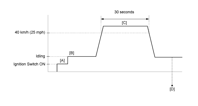
DTC P0461 Fuel Level Sensor "A" Circuit Range / Performance |
DTC P0462 Fuel Level Sensor "A" Circuit Low |
DTC P0463 Fuel Level Sensor "A" Circuit High |
| DTC No. | DTC Detection Condition | Trouble Area |
| P0461 | Despite consuming a certain amount of fuel, the change in the resistance value of the fuel sender gauge is below the threshold. (1 trip detection logic) |
|
| P0462 | The resistance value of the fuel sender gauge is below the threshold. (2 trip detection logic) |
|
| P0463 | The resistance value of the fuel sender gauge exceeds the threshold. (2 trip detection logic) |
|
| Related DTCs | P0461: Fuel level sensor stuck P0462: Fuel level sensor range check (Low Resistance) P0463: Fuel level sensor range check (High Resistance) |
| Required sensors/Components (Main) | Fuel sender gauge |
| Frequency of operation | Continuous |
| Duration | 10 seconds: P0461 30 seconds: P0462, P0463 |
| MIL operation | 50 miles of driving: P0461 2 driving cycles: P0462, P0463 |
| Sequence of operation | None |
| Monitor runs whenever following DTCs not stored | None |
| Battery voltage | 8.0 V or higher |
| Ignition switch | ON |
| Lost communication with IPC control module (U0155) | Not detected |
| Monitor runs whenever following DTCs not stored | None |
| Battery voltage | 8 V or higher |
| Ignition switch | ON |
| Time after ignition switch turned from off to ON | 2 seconds or more |
| Starter | OFF |
| Vehicle speed | 40 km/h (24.86 mph) or higher for 30 seconds or more |
| Vehicle speed sensor circuit failure (P0500) | Not detected |
| Lost communication with IPC control module (U0155) | Not detected |
| The difference between the fuel level sensor maximum and fuel level sensor minimum is less than 28 Ω | The cumulative volume of injected fuel 16 L or more |
| Fuel sender gauge resistance | Less than 35 Ω |
| Fuel sender gauge resistance | More than 816 Ω |
| Fuel sender gauge resistance | Varies between 115 and 510 Ω |
| Techstream Display | Description |
| NORMAL |
|
| ABNORMAL |
|
| INCOMPLETE |
|
| N/A |
|
| 1.CHECK FUEL SENDER GAUGE ASSEMBLY (POWER SOURCE VOLTAGE) |
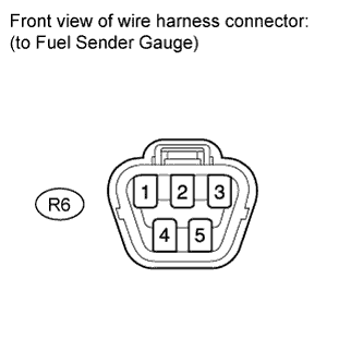 |
Disconnect the R6 gauge connector.
Turn the ignition switch to ON.
Measure the voltage according to the value(s) in the table below.
| Tester Connection | Switch Condition | Specified Condition |
| R6-2 - R6-3 | Ignition switch ON | 10 kΩ or higher |
|
| ||||
| OK | |
 |
| 2.CHECK HARNESS AND CONNECTOR (FUEL SENDER GAUGE - COMBINATION METER) |
Disconnect the J28 meter connector.
Disconnect the R6 gauge connector.
Measure the resistance according to the value(s) in the table below.
| Tester Connection | Condition | Specified Condition |
| J28-12 (L) - R6-2 | Always | Below 1 Ω |
| J28-39 (E3) - R6-3 | ||
| J28-40 (E1) - Body ground | ||
| J28-12 (L) or R6-2 - Body ground | Always | 10 kΩ or higher |
|
| ||||
| OK | |
|
| 3.INSPECT FUEL SENDER GAUGE ASSEMBLY |
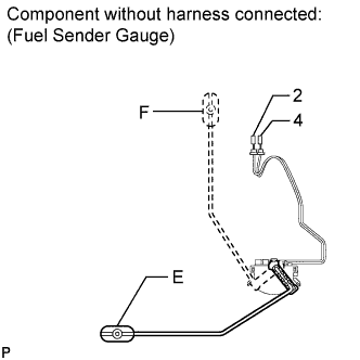 |
Remove the fuel sender gauge (Click here).
Measure the resistance according to the value(s) in the table below.
| Tester Connection | Condition | Specified Condition |
| 2 - 4 | Float level is F (upper) | 111 to 119 Ω |
| Float level is E (lower) | 506 to 514 Ω |
Check that the float moves smoothly.
|
| ||||
| OK | |
|
| 4.READ VALUE USING TECHSTREAM (ALCOHOL DENSITY ESTIMATE, SHORT FT, LONG FT) [STEP *1] |
Connect the Techstream to the DLC3.
Turn the ignition switch to ON.
Turn the Techstream on.
Drive the vehicle in accordance with the driving pattern described in Confirmation Driving Pattern.
Make sure that the Data List item "Alcohol Density Learning" is "Compl".
Enter the following menus: Powertrain / Engine and ECT / Data List / Alcohol Density Estimate, Short FT and Long FT.
Check the data list values, and then write them down.
| NEXT | |
|
| 5.CONFIRM ALCOHOL CONCENTRATION IN FUEL [STEP *2] |
Confirm the alcohol concentration in the fuel .
Write down the alcohol concentration in the fuel.
| NEXT | |
|
| 6.CONFIRM LEARNED VALUE |
Use the following formula to calculate the difference between the learned value from step *1 and the actual alcohol concentration in the fuel from step *2.
| Result | Proceed to |
| Difference is 10% or more | A |
| Difference is less than 10% | B |
|
| ||||
| A | |
|
| 7.CONFIRM LEARNED VALUE |
Use the following formula to calculate the difference between the learned values from step *1 and the actual alcohol concentration in the fuel from step *2.
| Result | Proceed to |
| Difference is 35% or more | A |
| Difference is 11 to 34% | B |
| Difference is 10% or less | C |
|
| ||||
|
| ||||
| A | |
|
| 8.CHECK FUEL INJECTION SYSTEM |
Check the fuel injection system (Click here).
|
| ||||
| 9.CONFIRM ALCOHOL CONCENTRATION IN FUEL |
Confirm the actual alcohol concentration in the fuel from step *2.
| Result | Proceed to |
| Alcohol concentration is more than 20% | A |
| Alcohol concentration is 20% or less | B |
|
| ||||
| A | |
|
| 10.REPLACE FUEL |
Replace the fuel with E0 gasoline (replace approximately 20 liters (5 gallons) of fuel).
Disconnect the cable from the negative (-) battery terminal for more than 1 minute.
|
| ||||
| 11.ADD FUEL |
Disconnect the cable from the negative (-) battery terminal for more than 1 minute.
Add at least 8 liters (2 gallons) of fuel.
Make sure that the Data List item "Alcohol Density Learning" is "Incmpl".
|
| ||||
| 12.PERFORM INITIALIZATION (FUEL DENSITY LEARNING VALUE RESET) |
Perform initialization (Fuel Density Learning Value Reset).
| NEXT | |
|
| 13.CONFIRM LEARNED VALUE |
Drive the vehicle in accordance with the driving pattern described in Confirmation Driving Pattern.
Make sure that the Data List item "Alcohol Density Learning" is "Compl".
Enter the following menus: Powertrain / Engine and ECT / Data List / Alcohol Density Estimate, Short FT and Long FT.
Check the data list values, and then write them down.
Confirm the alcohol concentration in the fuel .
Write down the alcohol concentration in the fuel.
Use the following formula to calculate the difference between the current learned value and the actual alcohol concentration in the fuel.
| Result | Specified Condition |
| Difference between actual alcohol concentration and Alcohol Density Estimate | Less than 10% |
| Short FT and Long FT | Between -35% and 35% |
|
| ||||
| OK | ||
 | ||
| ||

