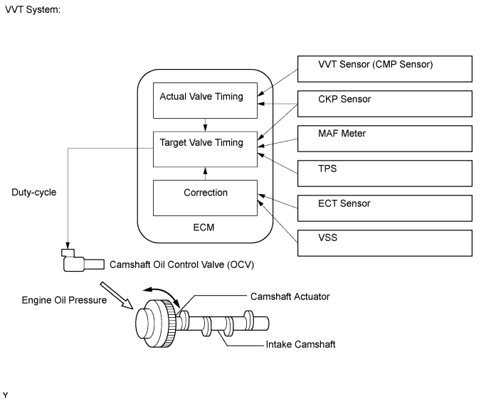
DTC P0010 Camshaft Position "A" Actuator Circuit (Bank 1) |
DTC P0020 Camshaft Position "A" Actuator Circuit (Bank 2) |
| DTC No. | DTC Detection Condition | Trouble Area |
| P0010 | Open or short in OCV (for intake side of bank 1) circuit (1 trip detection logic) |
|
| P0020 | Open or short in OCV (for intake side of bank 2) circuit (1 trip detection logic) |
|
| Related DTCs | P0010: VVT OCV range check (Bank 1) P0020: VVT OCV range check (Bank 2) |
| Required Sensors/Components (Main) | VVT OCV |
| Required Sensors/Components (Related) | - |
| Frequency of Operation | Continuous |
| Duration | 1 second |
| MIL Operation | Immediate |
| Sequence of Operation | None |
| Monitor runs whenever following DTCs not present | None |
| All of following conditions met | - |
| Starter | OFF |
| Ignition switch | ON |
| Time after ignition switch off to ON | 0.5 seconds or more |
| One of following conditions met | - |
| A. All of following conditions met | - |
| Battery voltage | 11 to 13 V |
| Target duty ratio | Less than 70% |
| B. All of following conditions met | - |
| Battery voltage | 13 V or more |
| Target duty ratio | Less than 80% |
| Current cut status | Not cut |
| Output duty cycle | 100% or more |
| Output duty cycle | 3% or less |
| VVT OCV duty cycle | 3 to 100% |
| Tester Display | Description |
| NORMAL |
|
| ABNORMAL |
|
| INCOMPLETE |
|
| N/A |
|
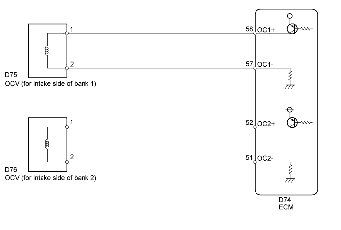
| 1.CHECK FOR DTC |
Clear DTCs after recording the freeze frame data and DTCs (Click here).
Turn the ignition switch off.
Allow the engine to idle and check for DTCs.
Check that P0010 or P0020 is not present.
|
| ||||
| OK | ||
 | ||
| ||
| 2.INSPECT CAMSHAFT OIL CONTROL VALVE |
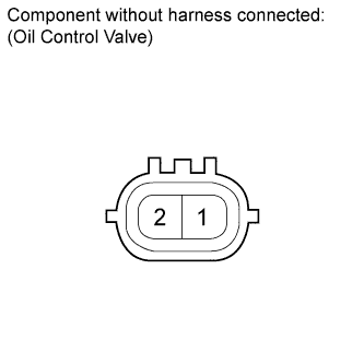 |
Disconnect the OCV connector.
Measure the resistance according to the value(s) in the table below.
| Tester Connection | Condition | Specified Condition |
| 1 - 2 | 20°C (68°F) | 6.9 to 7.9 Ω |
|
| ||||
| OK | |
 |
| 3.CHECK HARNESS AND CONNECTOR (OCV - ECM) |
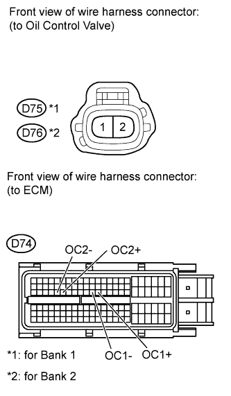 |
Disconnect the OCV connector.
Disconnect the ECM connector.
Measure the resistance according to the value(s) in the table below.
| Tester Connection | Condition | Specified Condition |
| D75-1 - D74-58 (OC1+) | Always | Below 1 Ω |
| D75-2 - D74-57 (OC1-) | Always | Below 1 Ω |
| D76-1 - D74-52 (OC2+) | Always | Below 1 Ω |
| D76-2 - D74-51 (OC2-) | Always | Below 1 Ω |
| D75-1 or D74-58 (OC1+) - Body ground | Always | 10 kΩ or higher |
| D75-2 or D74-57 (OC1-) - Body ground | Always | 10 kΩ or higher |
| D76-1 or D74-52 (OC2+) - Body ground | Always | 10 kΩ or higher |
| D76-2 or D74-51 (OC2-) - Body ground | Always | 10 kΩ or higher |
|
| ||||
| OK | ||
| ||
| ||

