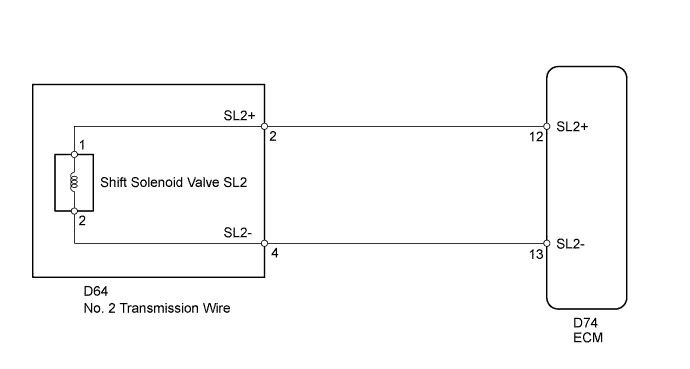
DTC P0778 Pressure Control Solenoid "B" Electrical (Shift Solenoid Valve SL2) |
| DTC Code | DTC Detection Condition | Trouble Area |
| P0778 | The ECM checks for an open or short in the shift solenoid valve SL2 circuit while driving and shifting gears (1 trip detection logic) Output signal duty ratio equals to 100%
|
|
| Related DTCs | P0778: Shift solenoid valve SL2/Range check |
| Required sensors/Components | Shift solenoid valve SL2 |
| Frequency of operation | Continuous |
| Duration | 1 second |
| MIL operation | Immediately |
| Sequence of operation | None |
| The monitor will run whenever the following DTCs are not present | None |
| Ignition switch | ON |
| Starter | OFF |
| Solenoid current cut status | Not cut |
| Battery voltage | 11 V or more |
| Solenoid status from solenoid driver MIC | Fail |
| Output signal duty | Less than 100% |
| ECM gear shift command | 1st | 2nd | 3rd | 4th | 5th | 6th |
| Shift solenoid valve SL2 | ON | ON | ON | ON | OFF | OFF |
| 1.INSPECT NO. 2 TRANSMISSION WIRE (SHIFT SOLENOID VALVE SL2) |
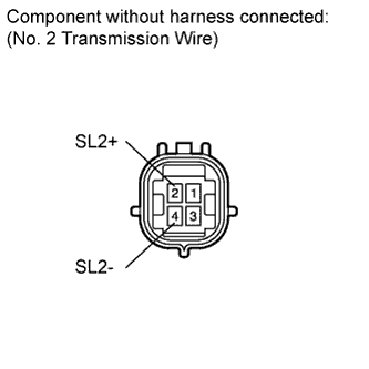 |
Disconnect the D64 No. 2 transmission wire connector.
Measure the resistance according to the value(s) in the table below.
| Tester Connection | Condition | Specified Condition |
| 2 (SL2+) - 4 (SL2-) | 20°C (68°F) | 5.0 to 5.6 Ω |
| 2 (SL2+) - Body ground | Always | 10 kΩ or higher |
| 4 (SL2-) - Body ground | Always | 10 kΩ or higher |
|
| ||||
| OK | |
 |
| 2.CHECK HARNESS AND CONNECTOR (NO. 2 TRANSMISSION WIRE - ECM) |
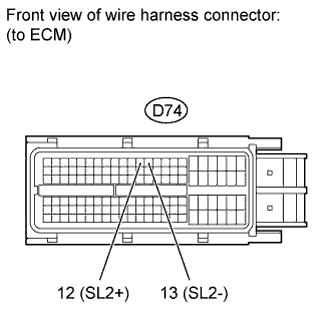 |
Disconnect the D74 ECM connector.
Measure the resistance according to the value(s) in the table below.
| Tester Connection | Condition | Specified Condition |
| D74-12 (SL2+) - D74-13 (SL2-) | 20°C (68°F) | 5.0 to 5.6 Ω |
| D74-12 (SL2+) - Body ground | Always | 10 kΩ or higher |
| D74-13 (SL2-) - Body ground | Always | 10 kΩ or higher |
| Result | Proceed to |
| NG | A |
| OK (for 3UR-FE) | B |
| OK (for 3UR-FBE) | C |
|
| ||||
|
| ||||
| A | ||
 | ||
| ||
| 3.INSPECT SHIFT SOLENOID VALVE SL2 |
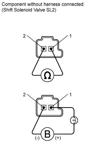 |
Remove shift solenoid valve SL2.
Measure the resistance according to the value(s) in the table below.
| Tester Connection | Condition | Specified Condition |
| 1 - 2 | 20°C (68°F) | 5.0 to 5.6 Ω |
Connect the battery's positive (+) lead with a 21 W bulb to terminal 1 and the negative (-) lead to terminal 2 of the solenoid valve connector. Then check that the valve moves and makes an operating noise.
|
| ||||
| OK | ||
| ||
| ||

