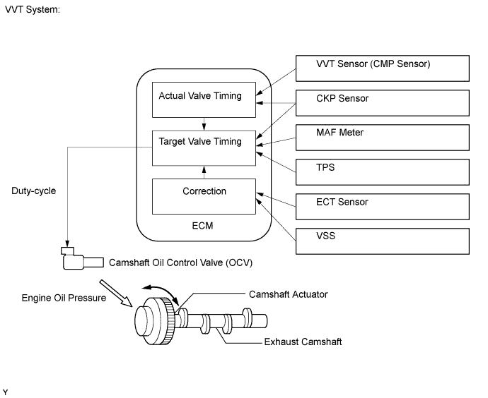
DTC P0014 Camshaft Position "B" - Timing Over-Advanced or System Performance (Bank 1) |
DTC P0015 Camshaft Position "B" - Timing Over-Retarded (Bank 1) |
DTC P0024 Camshaft Position "B" - Timing Over-Advanced or System Performance (Bank 2) |
DTC P0025 Camshaft Position "B" - Timing Over-Retarded (Bank 2) |
| DTC No. | DTC Detection Condition | Trouble Area |
| P0014 P0024 | Exhaust valve timing is not adjusted in valve timing advance range (2 trip detection logic) |
|
| P0015 P0025 | Exhaust valve timing is not adjusted in valve timing retard range (1 trip detection logic) |
|
| Related DTCs | P0014: Advanced camshaft timing (for Bank 1) P0015: Retarded camshaft timing (for Bank 1) P0024: Advanced camshaft timing (for Bank 2) P0025: Retarded camshaft timing (for Bank 2) |
| Required sensors/Components (Main) | VVT OCV and VVT Actuator |
| Required sensors/Components (Related) | Crankshaft position sensor, Camshaft position sensor and Engine coolant temperature sensor |
| Frequency of operation | Continuous |
| Duration | Within 10 seconds |
| MIL operation | Advanced camshaft timing: 2 driving cycles Retarded camshaft timing: Immediate |
| Sequence of operation | None |
| Monitor runs whenever following DTCs are not present | P0013, P0023 (Exhaust VVT oil control valve) P0017, P0019 (Exhaust VVT system - Misalignment) P0102, P0103 (Mass air flow meter) P0107, P0108 (Manifold absolute pressure) P0115, P0117, P0118 (Engine coolant temperature sensor) P0125 (Insufficient coolant temperature for closed loop fuel control) P0335 (Crankshaft position sensor) P1340 (Camshaft position sensor) |
| Battery voltage | 11 V or more |
| Engine RPM | 500 to 4000 rpm |
| Engine coolant temperature | 75 to 100°C (167 to 212°F) |
| Both conditions are met: | - |
| Deviation of actual valve timing and target valve timing | More than 5°CA (Crankshaft Angle) for 5 seconds or more after the VVT hold duty ratio learned value reaches the upper or lower limit. |
| Valve timing | No change at advanced valve timing |
| Both conditions are met: | - |
| Deviation of actual valve timing and target valve timing | More than 5°CA (Crankshaft Angle) for 5 seconds or more after the VVT hold duty ratio learned value reaches the upper or lower limit. |
| Valve timing | No change at retarded valve timing |
| Techstream Display | Description |
| NORMAL |
|
| ABNORMAL |
|
| INCOMPLETE |
|
| N/A |
|
| Abnormal Bank | Advanced Timing Over (Valve Timing Out of Specified Range) | Retarded Timing Over (Valve Timing Out of Specified Range) |
| Bank 1 | P0014 | P0015 |
| Bank 2 | P0024 | P0025 |
| 1.CHECK ANY OTHER DTCS OUTPUT (IN ADDITION TO DTC P0014, P0015, P0024 OR P0025) |
Connect the Techstream to the DLC3.
Turn the ignition switch to ON.
Turn the Techstream on.
Enter the following menus: Powertrain / Engine and ECT / Trouble Codes.
Read DTCs.
| Result | Proceed to |
| P0014, P0015, P0024 or P0025 | A |
| P0014, P0015, P0024 or P0025 and other DTCs | B |
|
| ||||
| A | |
 |
| 2.PERFORM ACTIVE TEST USING TECHSTREAM (OPERATE OCV) |
Connect the Techstream to the DLC3.
Turn the Techstream on.
Warm up the engine.
Enter the following menus: Powertrain / Engine and ECT / Active Test / Control the VVT Exhaust Linear (Bank1) or Control the VVT Exhaust Linear (Bank2).
Check the engine speed while operating the Oil Control Valve (OCV) using the Techstream.
| Tester Operation | Specified Condition |
| 0% | Normal engine speed |
| 100% | Engine idles roughly or stalls |
|
| ||||
| OK | |
|
| 3.CHECK WHETHER DTC OUTPUT RECURS (DTC P0014, P0015, P0024 OR P0025) |
Connect the Techstream to the DLC3.
Turn the Techstream on.
Clear DTCs (Click here).
Warm up the engine.
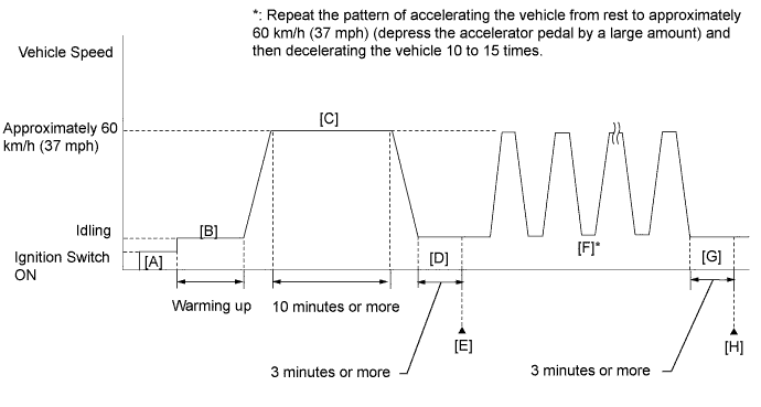
Drive the vehicle in accordance with the driving pattern described in the Confirmation Driving Pattern.
Read the output pending DTCs using the Techstream.
|
| ||||
| OK | ||
 | ||
| ||
| 4.CHECK VALVE TIMING (CHECK FOR LOOSENESS IN TIMING CHAIN OR JUMPED TOOTH) |
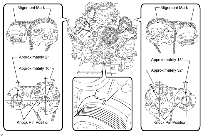
Remove the cylinder head cover LH and RH.
Turn the crankshaft pulley, and align its groove with the alignment mark "0" of the timing chain cover.
Check that the alignment marks of the camshaft timing gears and camshaft timing exhaust gears are at the positions shown in the illustration.
|
| ||||
| OK | |
|
| 5.INSPECT CAMSHAFT OIL CONTROL VALVE ASSEMBLY (OCV) |
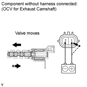 |
Remove the OCV (Click here).
Measure the resistance according to the value(s) in the table below.
| Tester Connection | Condition | Specified Condition |
| 1 - 2 | 20°C (68°F) | 6.9 to 7.9 Ω |
Apply positive (+) battery voltage to terminal 1 and negative (-) battery voltage to terminal 2. Check the valve operation.
|
| ||||
| OK | |
|
| 6.INSPECT OIL CONTROL VALVE FILTER |
Remove the oil control valve filter (Click here).
Check that the filter is not clogged.
|
| ||||
| OK | |
|
| 7.REPLACE CAMSHAFT TIMING EXHAUST GEAR ASSEMBLY |
Replace the camshaft timing exhaust gear assembly (Click here).
| NEXT | |
|
| 8.CHECK WHETHER DTC OUTPUT RECURS |
Connect the Techstream to the DLC3.
Turn the Techstream on.
Clear DTCs (Click here).
Warm up the engine.
Drive the vehicle in accordance with the driving pattern described in the Confirmation Driving Pattern.
Read the output pending DTCs using the Techstream.
|
| ||||
| OK | ||
| ||
| ||

