Measure the voltage and resistance according to the value(s) in the table below.
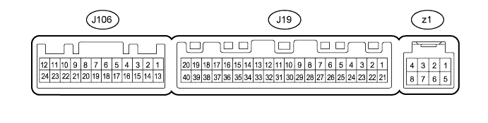
| Terminal No. (Symbol) | Wiring Color | Terminal Description | Condition | Specified Condition |
| J106-9 (SVDB) - Body ground | R - Body ground | Output climate control signal (Driver side) | Ignition switch ON Seat heater switch LH on | Pulse generation (see waveform) |
| J106-10 (SVPB) - Body ground | BE - Body ground | Output climate control signal (Front passenger side) | Ignition switch ON Seat heater switch RH on | Pulse generation (see waveform) |
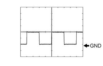
Using an oscilloscope, check waveform.
Measurement Condition Item Content Terminal No. (Symbol) J106-9 (SVDB) - Body ground
J106-10 (SVPB) - Body groundTool Setting 2 V/DIV., 500 μsec/DIV. Condition Ignition switch ON
Seat heater switch on
 |