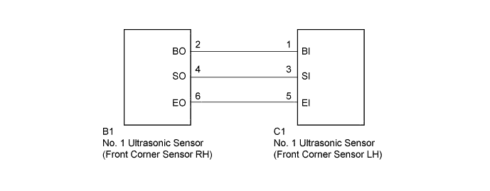
INTUITIVE PARKING ASSIST SYSTEM > Front Clearance Sonar Sensor LH Circuit |
| 1.REPLACE NO. 1 ULTRASONIC SENSOR (FRONT CORNER SENSOR LH) |
Remove the No. 1 ultrasonic sensor (front corner sensor LH) (Click here).
Inspect the No. 1 ultrasonic sensor (front corner sensor LH) (Click here)
|
| ||||
| OK | |
 |
| 2.CHECK HARNESS AND CONNECTOR (FRONT CORNER SENSOR LH - FRONT CORNER SENSOR RH) |
Disconnect the C1 No. 1 ultrasonic sensor (front corner sensor LH) connector.
Disconnect the B1 No. 1 ultrasonic sensor (front corner sensor RH) connector.
Measure the resistance according to the value(s) in the table below.
| Tester Connection | Condition | Specified Condition |
| C1-1 (BI) - B1-2 (BO) | Always | Below 1 Ω |
| C1-3 (SI) - B1-4 (SO) | Always | Below 1 Ω |
| C1-5 (EI) - B1-6 (EO) | Always | Below 1 Ω |
| C1-1 (BI) - Body ground | Always | 10 kΩ or higher |
| C1-3 (SI) - Body ground | Always | 10 kΩ or higher |
| C1-5 (EI) - Body ground | Always | 10 kΩ or higher |
|
| ||||
| OK | ||
 | ||
| ||
