KNOCK SENSOR > INSTALLATION |
| 1. INSTALL KNOCK SENSOR |
![]() |
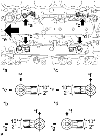
Install the 4 knock sensors with the 4 bolts so that the knock sensors are angled as shown in the illustration.
| *a | Bank 2 Sensor 1 |
| *b | Bank 1 Sensor 1 |
| *c | Bank 2 Sensor 2 |
| *d | Bank 1 Sensor 2 |
| *e | Front |
| *f | Upper |
| *g | Rear |
Connect the 4 knock sensor connectors.
| 2. INSTALL SEPARATOR CASE |
Install the separator case with the 4 bolts.
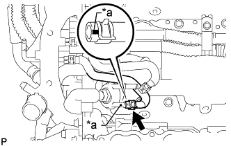
| 3. CONNECT NO. 10 WATER BY-PASS HOSE |
![]() |
Connect the No. 10 water by-pass hose to the separator case, and slide the clamp to secure the hose.
| *a | White Mark |
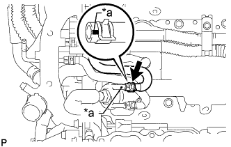
| 4. CONNECT NO. 9 WATER BY-PASS HOSE |
![]() |
Connect the No. 9 water by-pass hose to the separator case, and slide the clamp to secure the hose.
| *a | Pink Mark |
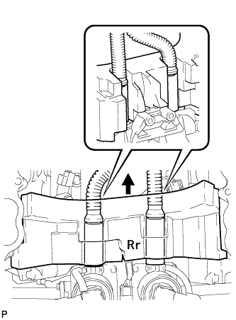
| 5. INSTALL NO. 1 ENGINE COVER |
![]() |
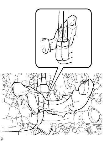
| 6. INSTALL NO. 2 CYLINDER HEAD COVER |
![]() |
| 7. INSTALL INTAKE MANIFOLD |