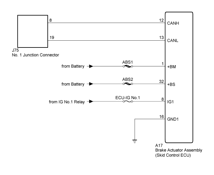
CAN COMMUNICATION SYSTEM > Skid Control ECU Communication Stop Mode |
| Detection Item | Symptom | Trouble Area |
| Skid Control ECU Communication Stop Mode | Either condition is met:
|
|
| 1.PRECAUTION |
| NEXT | |
 |
| 2.DISCONNECT CABLE FROM NEGATIVE BATTERY TERMINAL |
Disconnect the cable from the negative (-) battery terminal before measuring the resistances of the CAN main wire and the CAN branch wire.
| NEXT | |
|
| 3.CHECK FOR OPEN IN CAN BUS WIRE (SKID CONTROL ECU CAN BRANCH WIRE) |
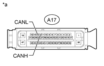 |
Disconnect the A17 brake actuator assembly (skid control ECU) connector.
Measure the resistance according to the value(s) in the table below.
| Tester Connection | Switch Condition | Specified Condition |
| A17-12 (CANH) - A17-13 (CANL) | Ignition switch off | 54 to 69 Ω |
| *a | Front view of wire harness connector (to Brake Actuator Assembly [Skid Control ECU]) |
|
| ||||
| OK | |
|
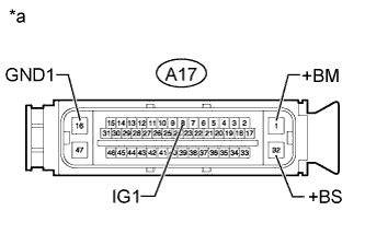
| 4.CHECK HARNESS AND CONNECTOR (SKID CONTROL ECU - BATTERY AND BODY GROUND) |
 |
Connect the cable to the negative (-) battery terminal.
Measure the resistance according to the value(s) in the table below.
| Tester Connection | Condition | Specified Condition |
| A17-16 (GND1) - Body ground | Always | Below 1 Ω |
Measure the voltage according to the value(s) in the table below.
| Tester Connection | Condition | Specified Condition |
| A17-1 (+BM) - Body ground | Always | 11 to 14 V |
| A17-32 (+BS) - Body ground | Always | 11 to 14 V |
| A17-8 (IG1) - Body ground | Ignition switch ON | 11 to 14 V |
| *a | Front view of wire harness connector (to Brake Actuator Assembly [Skid Control ECU]) |
|
| ||||
| OK | ||
 | ||
| ||
