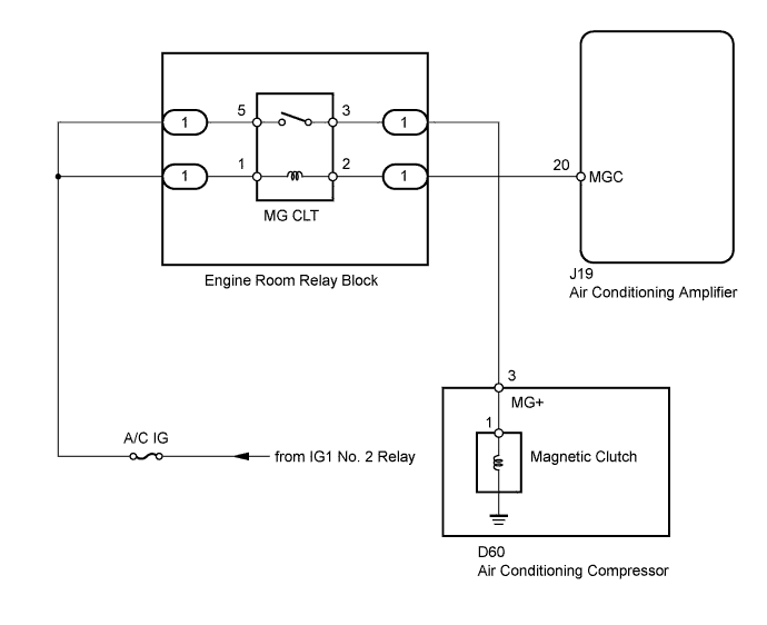
AIR CONDITIONING SYSTEM (for Manual Air Conditioning System) > Air Conditioning Compressor Magnetic Clutch Circuit |
| 1.READ VALUE USING TECHSTREAM (A/C SIGNAL) |
Use the Data List to check if the air conditioning signal is functioning properly.
| Tester Display | Measurement Item / Range | Normal Condition | Diagnostic Note |
| A/C Signal | A/C switch signal / ON or OFF | ON: A/C switch ON OFF: A/C switch OFF | - |
|
| ||||
| OK | ||
 | ||
| ||
| 2.INSPECT FUSE (A/C IG) |
Remove the A/C IG fuse from the main body ECU.
Measure the resistance according to the value(s) in the table below.
| Tester Connection | Condition | Specified Condition |
| A/C IG fuse | Always | Below 1 Ω |
|
| ||||
| OK | |
 |
| 3.CHECK HARNESS AND CONNECTOR (ENGINE ROOM RELAY BLOCK - BATTERY) |
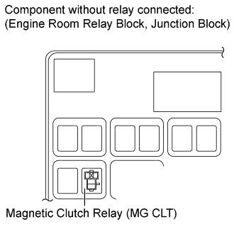 |
Remove the magnetic clutch relay (MG CLT) from the engine room relay block, junction block.
Measure the voltage according to the value(s) in the table below.
| Tester Connection | Switch Condition | Specified Condition |
| Engine room relay block, junction block magnetic clutch relay terminal 5 - Body ground | Ignition switch ON | 11 to 14 V |
| Ignition switch off | Below 1 V | |
| Engine room relay block, junction block magnetic clutch relay terminal 1 - Body ground | Ignition switch ON | 11 to 14 V |
| Ignition switch off | Below 1 V |
|
| ||||
| OK | |
|
| 4.INSPECT MAGNETIC CLUTCH RELAY (MG CLT) |
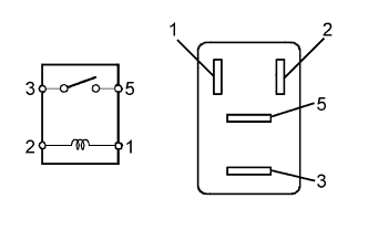 |
Remove the magnetic clutch relay from the engine room relay block, junction block.
Measure the resistance according to the value(s) in the table below.
| Tester Connection | Condition | Specified Condition |
| 3 - 5 | When battery voltage is not applied between terminals 1 and 2 | 10 kΩ or higher |
| When battery voltage is applied to terminals 1 and 2 | Below 1 Ω |
|
| ||||
| OK | |
|
| 5.CHECK HARNESS AND CONNECTOR (AIR CONDITIONING AMPLIFIER - BATTERY) |
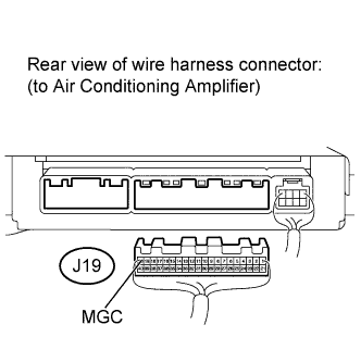 |
Disconnect the J19 air conditioning amplifier connector.
Measure the voltage according to the value(s) in the table below.
| Tester Connection | Switch Condition | Specified Condition |
| J19-20 (MGC) - Body ground | Ignition switch OFF | Below 1 V |
| Ignition switch ON | 11 to 14 V |
|
| ||||
| OK | |
|
| 6.CHECK AIR CONDITIONING AMPLIFIER (MGC VOLTAGE) |
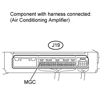 |
Reconnect the J19 air conditioning amplifier connector.
Measure the voltage according to the value(s) in the table below.
| Tester Connection | Switch Condition | Specified Condition |
| J19-20 (MGC) - Body ground | Engine is running Blower switch LO A/C switch ON | Below 1 V |
| Engine is running Blower switch LO A/C switch OFF | 11 to 14 V |
|
| ||||
| OK | |
|
| 7.INSPECT AIR CONDITIONING COMPRESSOR (COMPRESSOR HARNESS) |
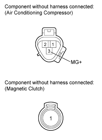 |
Disconnect the D60 air conditioning compressor connector.
Disconnect the magnetic clutch connector.
Measure the resistance according to the value(s) in the table below.
| Tester Connection | Condition | Specified Condition |
| 3 (MG+) - 1 | Always | Below 1 Ω |
| 3 (MG+) or 1 - Body ground | Always | 10 kΩ or higher |
|
| ||||
| OK | |
|
| 8.INSPECT MAGNETIC CLUTCH |
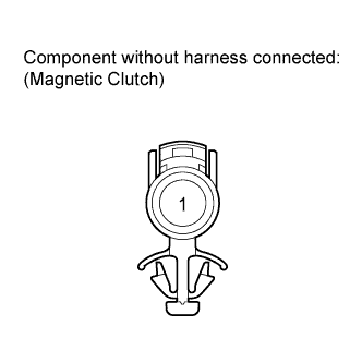 |
Measure the resistance according to the value(s) in the table below.
| Tester Connection | Condition | Specified Condition |
| 1 - Body ground | Always | 3.4 to 3.8 Ω |
When connector terminal 1 is connected to the positive (+) battery terminal, check that the following occurs: 1) the magnetic clutch's operating sound can be heard, and 2) the magnetic clutch's hub and rotor lock.
| Result | Proceed to |
| OK | A |
| NG (for 1GR-FE) | B |
| NG (for 1UR-FE, 3UR-FE or 3UR-FBE) | C |
|
| ||||
|
| ||||
| A | |
|
| 9.CHECK HARNESS AND CONNECTOR (AIR CONDITIONING COMPRESSOR - ENGINE ROOM RELAY BLOCK) |
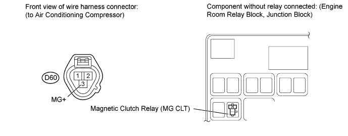
Disconnect the D60 air conditioning compressor connector.
Remove the magnetic clutch relay (MG CLT) from the engine room relay block, junction block.
Measure the resistance according to the value(s) in the table below.
| Tester Connection | Condition | Specified Condition |
| D60-3 (MG+) - Engine room relay block, junction block magnetic clutch relay terminal 3 | Always | Below 1 Ω |
| D60-3 (MG+) or Engine room relay block, junction block magnetic clutch relay terminal 3 - Body ground | Always | 10 kΩ or higher |
|
| ||||
| OK | ||
| ||
| ||

