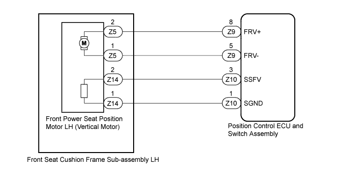
DTC B2652 Front Vertical Sensor Malfunction |
| DTC Code | DTC Detection Condition | Trouble Area |
| B2652 | The upward and downward lock detection position of the sensor is the same. |
|
| 1.PERFORM ACTIVE TEST USING TECHSTREAM (FRONT VERTICAL OPERATION) |
Connect the Techstream to the DLC3.
Turn the ignition switch to ON.
Turn the Techstream on.
Enter the following menus: Body Electrical / Driver Seat / Active Test.
Perform the Active Test according to the display on the Techstream.
| Tester Display | Test Part | Control Range | Diagnostic Note |
| Front Vertical Operation | Seat front vertical operation | Up / OFF / Down | - |
|
| ||||
| OK | |
 |
| 2.CHECK POSITION CONTROL ECU AND SWITCH ASSEMBLY (VERTICAL MOTOR CIRCUIT) |
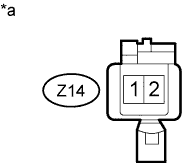 |
Disconnect the front seat cushion frame sub-assembly LH (vertical motor) connector.
Measure the voltage according to the value(s) in the table below.
| Tester Connection | Switch Condition | Specified Condition |
| Z14-1 - Z14-2 | Front vertical switch on | 4.8 to 5.1 V |
| *a | Front view of wire harness connector (to Front Seat Cushion Frame Sub-assembly LH [Vertical Motor]) |
|
| ||||
| OK | |
|
| 3.CHECK FRONT SEAT CUSHION FRAME SUB-ASSEMBLY LH (VERTICAL MOTOR) |
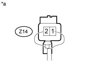 |
Reconnect the front seat cushion frame sub-assembly LH (vertical motor) connector.
Measure the voltage according to the value(s) in the table below.
| Tester Connection | Switch Condition | Specified Condition |
| Z14-2 - Body ground | Front vertical switch on | 4.5 to 4.8 V |
| *a | Component with harness connected (Front Seat Cushion Frame Sub-assembly LH [Vertical Motor]) |
|
| ||||
| OK | ||
 | ||
| ||
| 4.CHECK HARNESS AND CONNECTOR (POSITION CONTROL ECU AND SWITCH ASSEMBLY - FRONT SEAT CUSHION FRAME SUB-ASSEMBLY LH) |
Disconnect the Z10 position control ECU and switch assembly connector.
Measure the resistance according to the value(s) in the table below.
| Tester Connection | Condition | Specified Condition |
| Z10-3 (SSFV) - Z14-2 | Always | Below 1 Ω |
| Z10-1 (SGND) - Z14-1 | Always | Below 1 Ω |
| Z10-3 (SSFV) or Z14-2 - Body ground | Always | 10 kΩ or higher |
| Z10-1 (SGND) or Z14-1 - Body ground | Always | 10 kΩ or higher |
|
| ||||
| OK | ||
| ||
| ||
| 5.INSPECT FRONT SEAT CUSHION FRAME SUB-ASSEMBLY LH (VERTICAL MOTOR) |
Remove the front seat cushion frame sub-assembly LH (vertical motor) (Click here).
Inspect the front seat cushion frame sub-assembly LH (vertical motor) .
|
| ||||
| OK | |
|
| 6.CHECK HARNESS AND CONNECTOR (POSITION CONTROL ECU AND SWITCH ASSEMBLY - FRONT SEAT CUSHION FRAME SUB-ASSEMBLY LH) |
Disconnect the Z9 position control ECU and switch assembly connector.
Measure the resistance according to the value(s) in the table below.
| Tester Connection | Condition | Specified Condition |
| Z9-8 (FRV+) - Z5-2 | Always | Below 1 Ω |
| Z9-5 (FRV-) - Z5-1 | Always | Below 1 Ω |
| Z9-8 (FRV+) or Z5-2 - Body ground | Always | 10 kΩ or higher |
| Z9-5 (FRV-) or Z5-1 - Body ground | Always | 10 kΩ or higher |
|
| ||||
| OK | ||
| ||
| ||

