 |
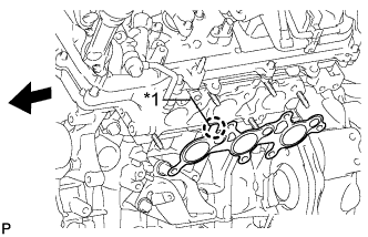
Install a new gasket to the cylinder head.
| *1 | Protrusion |
 | Front |
- NOTICE:
- Be careful of the installation direction.
EXHAUST MANIFOLD > INSTALLATION |
| 1. INSTALL EXHAUST MANIFOLD SUB-ASSEMBLY LH |
|
Install a new gasket to the cylinder head.
| *1 | Protrusion |
| Front |
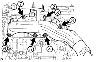 |
Temporarily install the manifold with the new nut labeled 1.
Install the remaining 5 new nuts and tighten the nuts in the sequence shown in the illustration.
| 2. INSTALL NO. 2 EXHAUST MANIFOLD HEAT INSULATOR |
Install the heat insulator with the 3 bolts.
| 3. INSTALL NO. 2 AIR TUBE |
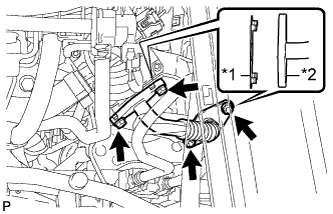 |
Install 2 new gaskets to the No. 2 air tube as shown in the illustration.
| *1 | New Gasket |
| *2 | No. 2 Air Tube |
Install the No. 2 air tube with the 2 bolts and 2 nuts.
| 4. INSTALL MANIFOLD STAY |
Install the manifold stay with the 3 bolts.
| 5. INSTALL EXHAUST MANIFOLD SUB-ASSEMBLY RH |
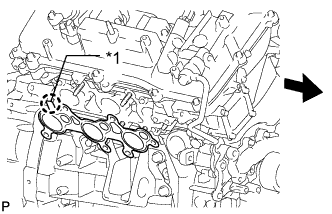 |
Install a new gasket to the cylinder head.
| *1 | Protrusion |
| Front |
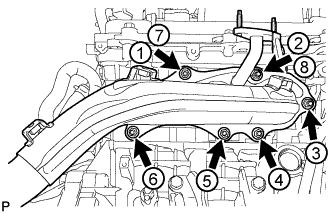 |
Temporarily install the manifold with the new nut labeled 1.
Install the remaining 5 new nuts and tighten the nuts in the sequence shown in the illustration.
| 6. INSTALL NO. 1 EXHAUST MANIFOLD HEAT INSULATOR |
Install the heat insulator with the 3 bolts.
| 7. INSTALL AIR TUBE |
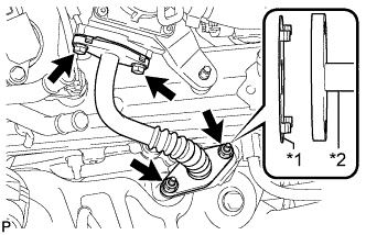 |
Install 2 new gaskets to the air tube as shown in the illustration.
| *1 | New Gasket |
| *2 | Air Tube |
Install the air tube with the 2 bolts and 2 nuts.
| 8. INSTALL NO. 2 MANIFOLD STAY |
Install the manifold stay with the 3 bolts.
Connect the wire harness connector.
| 9. INSTALL FRONT FENDER APRON SEAL REAR RH |
Install the fender apron seal with the 5 clips.
| 10. INSTALL FRONT FENDER APRON SEAL REAR LH |
Install the fender apron seal with the 5 clips.
| 11. INSTALL AIR CLEANER CASE SUB-ASSEMBLY |
Install the air cleaner case with the 2 bolts.
Attach the wire harness clamp.
Install the air cleaner filter element.
| 12. INSTALL AIR CLEANER CAP AND HOSE |
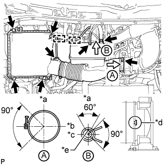 |
Install the air cleaner cap and hose.
| *a | Top |
| *b | Front |
| *c | RH Side |
| *d | Align cutout portion of hose with protrusion of throttle |
| *e | Paint Mark |
Attach the 4 hook clamps to install the air cleaner cap and hose.
Tighten the clamp.
Attach the 4 clamps and connect the ventilation hose, vacuum hose and mass air flow meter connector.
| 13. INSTALL FRONT EXHAUST PIPE ASSEMBLY |