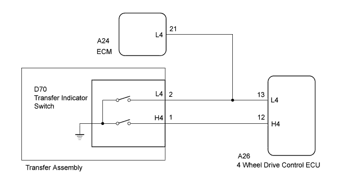
DTC P2772 Four Wheel Drive (4WD) Low Switch Circuit Range / Performance |
| Terminal | In 4H | Switching between 4H and 4L | In 4L |
| H4 | OFF (OPEN) | ON (GND) | ON (GND) |
| L4 | OFF (OPEN) | OFF (OPEN) | ON (GND) |
| DTC Code | DTC Detection Condition
| Trouble Area |
| P2772 |
|
|
| 1.CHECK HARNESS AND CONNECTOR (4 WHEEL DRIVE CONTROL ECU - TRANSFER INDICATOR SWITCH) |
Disconnect the A26 4 wheel drive control ECU connector.
Disconnect the D70 transfer indicator switch connector.
Disconnect the A24 ECM connector.
Measure the resistance according to the value(s) in the table below.
| Tester Connection | Condition | Specified Condition |
| A26-13 (L4) - D70-2 (L4) | Always | Below 1 Ω |
| A26-12 (H4) - D70-1 (H4) | Always | Below 1 Ω |
| A26-13 (L4), D70-2 (L4) or A24-21 (L4) - Body ground | Always | 10 kΩ or higher |
| A26-12 (H4) or D70-1 (H4) - Body ground | Always | 10 kΩ or higher |
| A26-13 (L4), D70-2 (L4) or A24-21 (L4) - A26-12 (H4) or D67-1 (H4) | Always | 10 kΩ or higher |
|
| ||||
| OK | |
 |
| 2.CHECK 4 WHEEL DRIVE CONTROL ECU (ECU OUTPUT VOLTAGE) |
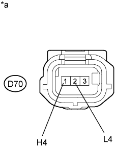 |
Disconnect the A24 ECM connector.
Disconnect the transfer indicator switch connector.
Measure the voltage according to the value(s) in the table below.
| Tester Connection | Switch Condition | Specified Condition |
| D70-2 (L4) - Body ground | Ignition switch ON | 4 to 6 V |
| D70-1 (H4) - Body ground | Ignition switch ON | 4 to 6 V |
| *a | Front view of wire harness connector (to Transfer Indicator Switch) |
|
| ||||
| OK | ||
 | ||
| ||
