DTC B1532 LVDS Signal Malfunction (from Extension Module) |
DTC B156C Extension Module Disconnected |
| DTC Code | DTC Detection Condition | Trouble Area |
| B1532 | When either condition below is met:.
|
|
| B156C |
| 1.CHECK FOR DTC |
Clear the DTCs (Click here).
Check for DTCs (Click here).
|
| ||||
| OK | ||
 | ||
| ||
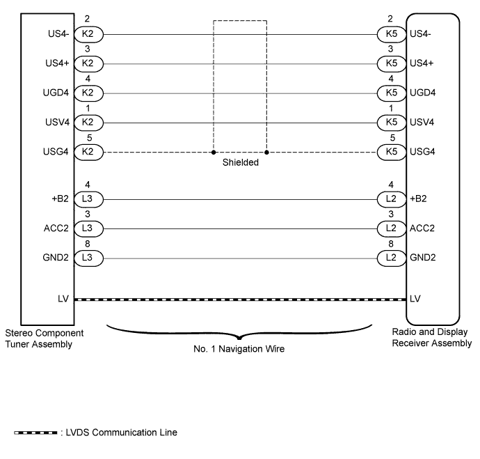
| 2.CHECK HARNESS AND CONNECTOR (RADIO AND DISPLAY RECEIVER ASSEMBLY - STEREO COMPONENT TUNER ASSEMBLY) |
Disconnect the K5 and L2 radio and display receiver assembly connectors.
Disconnect the K2 and L3 stereo component tuner assembly connectors.
Measure the resistance according to the value(s) in the table below.
| Tester Connection | Condition | Specified Condition |
| K5-1 (USV4) - K2-1 (USV4) | Always | Below 1 Ω |
| K5-2 (US4-) - K2-2 (US4-) | Always | Below 1 Ω |
| K5-3 (US4+) - K2-3 (US4+) | Always | Below 1 Ω |
| K5-4 (UGD4) - K2-4 (UGD4) | Always | Below 1 Ω |
| K5-5 (USG4) - K2-5 (USG4) | Always | Below 1 Ω |
| L2-4 (+B2) - L3-4 (+B2) | Always | Below 1 Ω |
| L2-3 (ACC2) - L3-3 (ACC2) | Always | Below 1 Ω |
| L2-8 (GND2) - L3-8 (GND2) | Always | Below 1 Ω |
| K5-1 (USV4) - Body ground | Always | 10 kΩ or higher |
| K5-2 (US4-) - Body ground | Always | 10 kΩ or higher |
| K5-3 (US4+) - Body ground | Always | 10 kΩ or higher |
| K5-4 (UGD4) - Body ground | Always | 10 kΩ or higher |
| K5-5 (USG4) - Body ground | Always | 10 kΩ or higher |
| L2-4 (+B2) - Body ground | Always | 10 kΩ or higher |
| L2-3 (ACC2) - Body ground | Always | 10 kΩ or higher |
| L2-8 (GND2) - Body ground | Always | 10 kΩ or higher |
| Result | Proceed to |
| OK | A |
| NG (for Column Shift Type) | B |
| NG (for Floor Shift Type) | C |
|
| ||||
|
| ||||
| A | |
 |
| 3.CHECK NO. 1 NAVIGATION WIRE (LVDS COMMUNICATION LINE) |
Replace the No. 1 navigation wire with a known good one.
Clear the DTCs (Click here).
Check for DTCs (Click here).
|
| ||||
| OK | ||
| ||
| ||
| 4.CHECK STEREO COMPONENT TUNER ASSEMBLY |
Replace the stereo component tuner assembly with a known good one.
Clear the DTCs (Click here).
Check for DTCs (Click here).
| Result | Proceed to |
| OK | A |
| NG (for Column Shift Type) | B |
| NG (for Floor Shift Type) | C |
|
| ||||
|
| ||||
| A | ||
| ||
| ||

