BODY WELD POINT FRONT DOOR OUTER PANEL CUT AND JOIN REPLACEMENT SECTIONS
Regular Cab
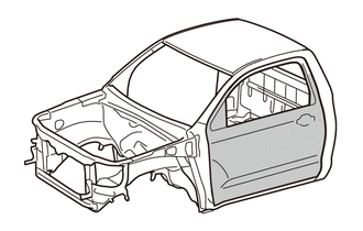
REMOVAL
| Symbol Meaning | |
|---|---|

|
Cut and Join Location |
After grinding off the hemming location, remove the outer panel.
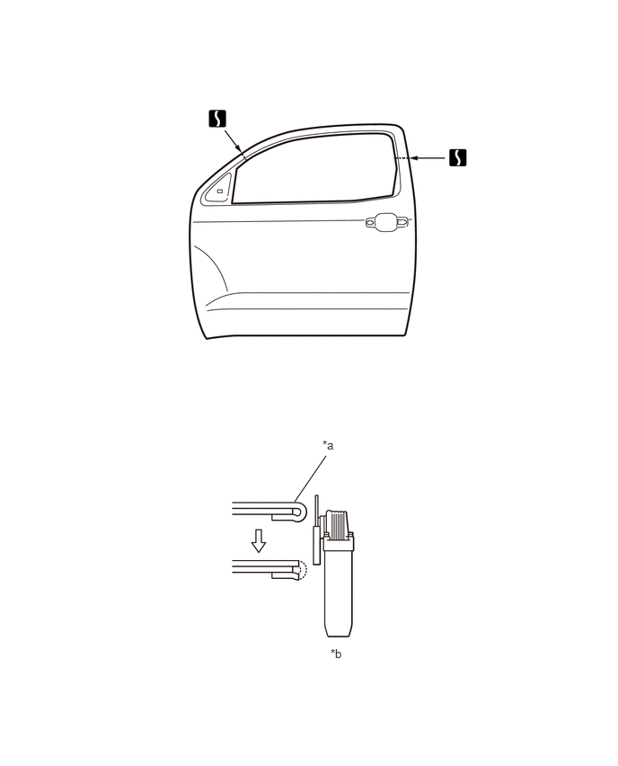
| *a | Hemming Location | *b | Disc Sander |
INSTALLATION
Before temporarily installing the new parts, apply body sealer to the reinforcement, side impact protection beam and backside of the new parts.
- HINT:
-
Apply sealer evenly about 10 mm (0.39 in.) from the flange and 3 mm (0.12 in.) in diameter on the outer panel and apply just enough sealer for the reinforcement and side impact protection beam to make contact.
Bend the flange hem about 30° with a hammer and dolly. Then, fasten tightly with a hemming tool.
- HINT:
- ·
Perform hemming in three steps, being careful not to warp the panel.
·If a hemming tool cannot be used, hem with a hammer and dolly.
After applying the top coat, apply anti-rust agent to the internal panel portion of the closed section structural weld points.
| Symbol Meaning | |
|---|---|

|
Butt Weld |

|
Spot MIG Weld |

|
Body Sealer |
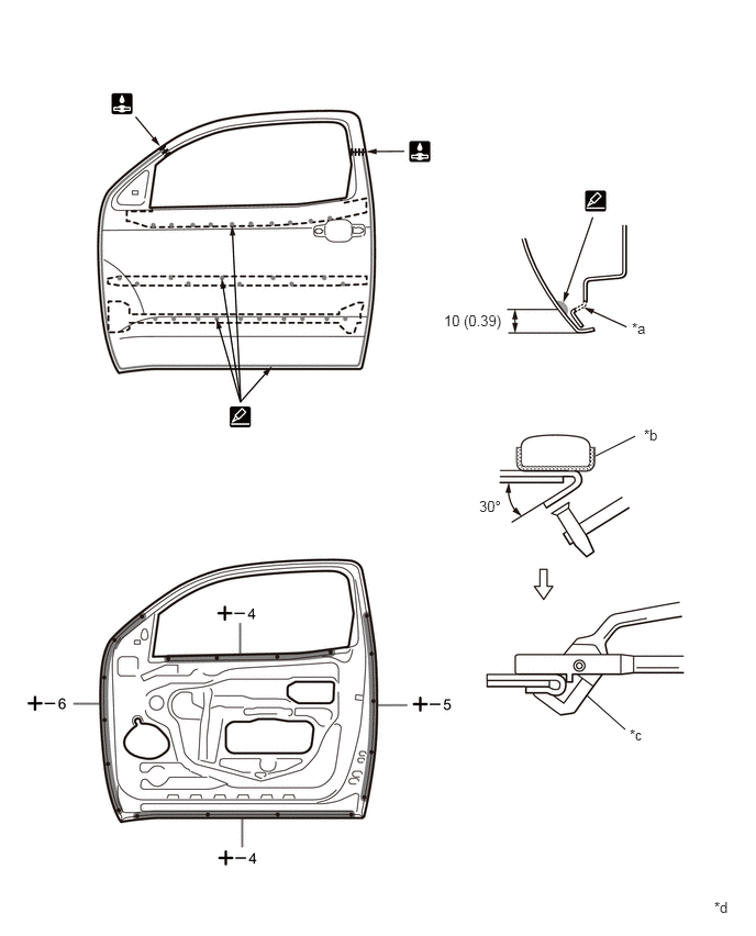
| *a | Do not close the drain hole. | *b | Cloth Tape |
| *c | Hemming Tool | *d | mm (in.) |
Ex. Regular Cab
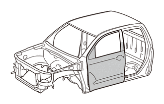
REMOVAL
| Symbol Meaning | |
|---|---|
|
|
Cut and Join Location |
After grinding off the hemming location, remove the outer panel.
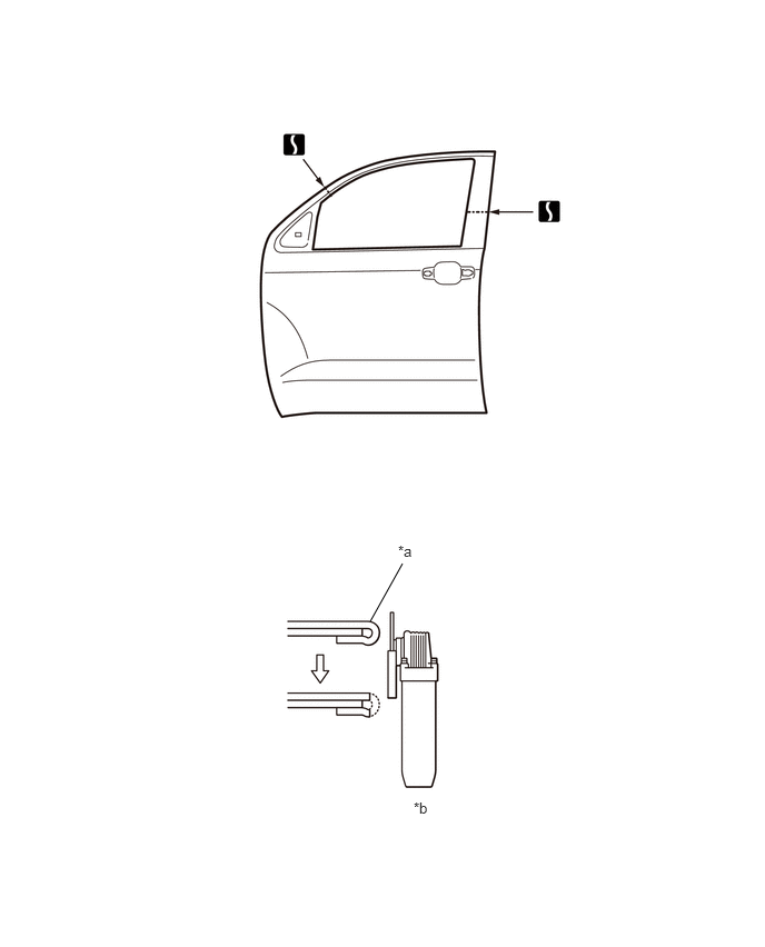
| *a | Hemming Location | *b | Disc Sander |
INSTALLATION
Before temporarily installing the new parts, apply body sealer to the reinforcement, side impact protection beam and backside of the new parts.
- HINT:
-
Apply sealer evenly about 10 mm (0.39 in.) from the flange and 3 mm (0.12 in.) in diameter on the outer panel and apply just enough sealer for the reinforcement and side impact protection beam to make contact.
Bend the flange hem about 30° with a hammer and dolly. Then, fasten tightly with a hemming tool.
- HINT:
- ·
Perform hemming in three steps, being careful not to warp the panel.
·If a hemming tool cannot be used, hem with a hammer and dolly.
After applying the top coat, apply anti-rust agent to the internal panel portion of the closed section structural weld points.
| Symbol Meaning | |
|---|---|
|
|
Butt Weld |
|
|
Spot MIG Weld |
|
|
Body Sealer |
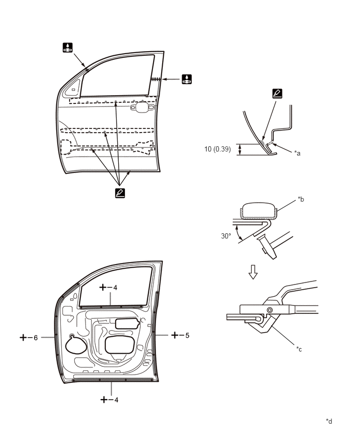
| *a | Do not close the drain hole. | *b | Cloth Tape |
| *c | Hemming Tool | *d | mm (in.) |