Home › General › BODY ELECTRICAL › MULTIPLEX COMMUNICATION
NM27M0U _V1 General _050233 BODY ELECTRICAL _0241755 MULTIPLEX COMMUNICATION UN GENERAL/CONTROL/DETAILS F

BODY ELECTRICAL  MULTIPLEX COMMUNICATION  GENERAL/CONTROL/DETAILS  CAN  


GENERAL


a.

The CAN (Controller Area Network) uses two different CAN buses: V bus for high-speed communication (500 kbps) and MS bus for medium-speed communication (250 kbps).

i.

The CAN has two terminating resistors of 120 Ω which are necessary for accurate judgment of communication on the main bus.


ii.

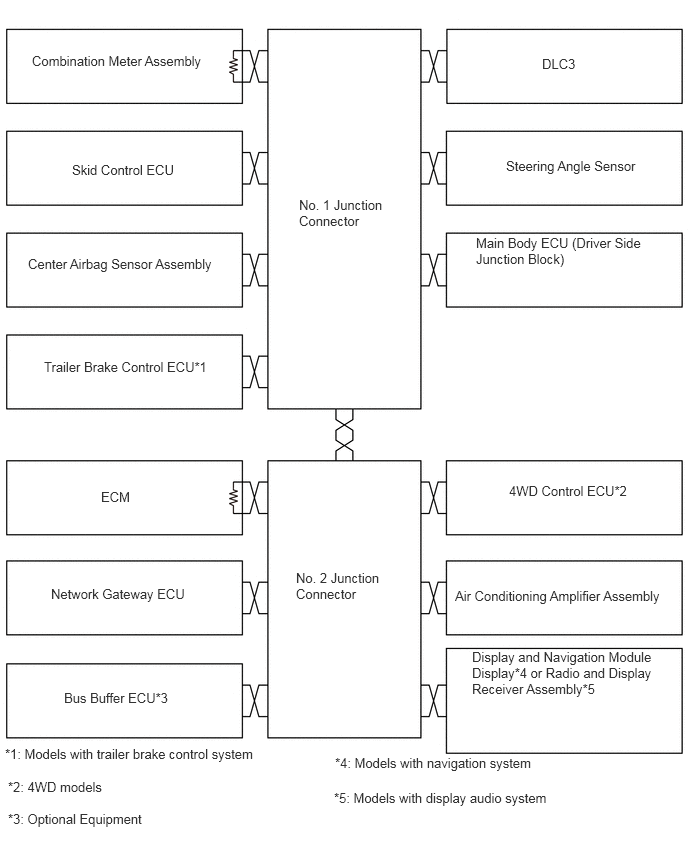
The terminating resistors for the V bus are located in the ECM and the combination meter (Meter ECU).


iii.

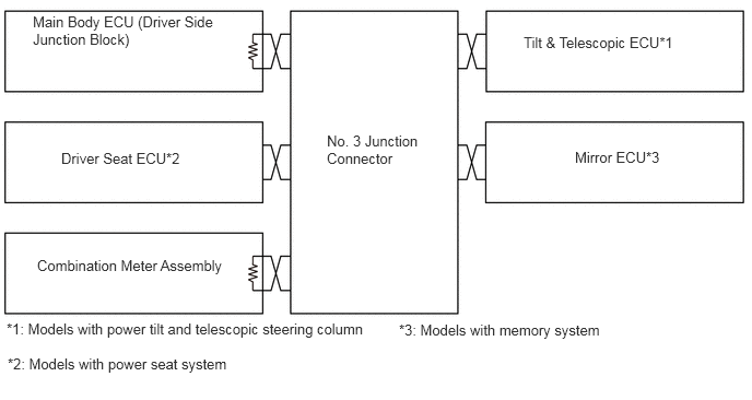
The terminating resistors for the MS bus are located in the Main Body ECU (Driver Side Junction Block) and the combination meter (Meter ECU).


iv.

Combination meter (Meter ECU) is connected to MS bus only for the termination resistor. The combination meter does not communicate using the MS bus.


v.

The Main Body ECU (Driver Side Junction Block) has a gateway function and is used to transmit data between the V bus and the MS bus.


b.

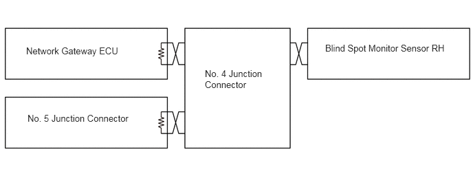
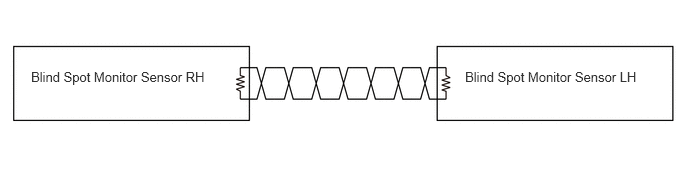
Wiring Diagram

V Bus
Y195596E01
5.646,0.583 6.313,0.938 0.667,0.354 10 false DLC3 5.271,1.646 6.938,2.052 1.667,0.406 10 false Steering Angle Sensor 4.958,2.448 6.813,3.156 1.854,0.708 10 false Main Body ECU (Driver Side Junction Block) 3.115,2.052 4.073,3.135 0.958,1.083 10 false No. 1 Junction Connector 0.333,0.552 2.344,0.969 2.01,0.417 10 false Combination Meter Assembly 0.75,1.688 2.26,2.073 1.51,0.385 10 false Skid Control ECU 0.292,2.667 2.438,3.146 2.146,0.479 10 false Center Airbag Sensor Assembly 0.458,3.74 2.323,4.198 1.865,0.458 10 false Trailer Brake Control ECU*1 1.052,5.094 1.719,5.479 0.667,0.385 10 false ECM 0.531,6.104 2.104,6.531 1.573,0.427 10 false Network Gateway ECU 0.667,7.188 2.125,7.604 1.458,0.417 10 false Bus Buffer ECU*3 3.083,5.938 4.042,6.885 0.958,0.948 10 false No. 2 Junction Connector 5.302,5.031 6.875,5.448 1.573,0.417 10 false 4WD Control ECU*2 4.74,6.125 7.073,6.521 2.333,0.396 10 false Air Conditioning Amplifier Assembly 4.917,6.76 6.885,7.813 1.969,1.052 10 false Display and Navigation Module Display*4 or Radio and Display Receiver Assembly*5 0.052,7.771 3.052,8.094 3,0.323 10 false *1: Models with trailer brake control system 0.083,8.115 2.281,8.427 2.198,0.313 10 false *2: 4WD models 3.49,7.865 6.052,8.188 2.563,0.323 10 false *4: Models with navigation system 3.479,8.229 6.292,8.604 2.813,0.375 10 false *5: Models with display audio system 0.083,8.448 2.281,8.792 2.198,0.344 10 false *3: Optional Equipment

V2 Bus (Models with Blind Spot Monitor System)
Y195597E01
0.396,0.688 2.115,1.104 1.719,0.417 10 false Network Gateway ECU 3.104,1.031 4.073,1.948 0.969,0.917 10 false No. 4 Junction Connector 4.927,0.646 6.979,1.094 2.052,0.448 10 false Blind Spot Monitor Sensor RH 0.417,1.708 2.135,2.125 1.719,0.417 10 false No. 5 Junction Connector

MS Bus
Y195598E01
4.99,0.323 7.01,0.74 2.021,0.417 10 false Tilt & Telescopic ECU*1 5.479,1.417 6.698,1.833 1.219,0.417 10 false Mirror ECU*3 3.115,1.26 4.083,2.417 0.969,1.156 10 false No. 3 Junction Connector 0.583,1.427 2.01,1.802 1.427,0.375 10 false Driver Seat ECU*2 0.354,2.448 2.313,2.854 1.958,0.406 10 false Combination Meter Assembly 0.073,3.385 3,3.74 2.927,0.354 10 false *2: Models with power seat system 0.063,3.052 3.76,3.375 3.698,0.323 10 false *1: Models with power tilt and telescopic steering column 3.802,3.063 6.24,3.406 2.438,0.344 10 false *3: Models with memory system 0.313,0.125 2.198,0.844 1.885,0.719 10 false Main Body ECU (Driver Side Junction Block)

Sensor Bus (Models with Blind Spot Monitor System)
Y195599E01
0.323,0.719 2.375,1.094 2.052,0.375 10 false Blind Spot Monitor Sensor RH 4.844,0.719 6.896,1.094 2.052,0.375 10 false Blind Spot Monitor Sensor LH


c.

There is no communication between the CAN and AVC-LAN because this multiplex communication system does not use the gateway function (transfer protocol function). The CAN and AVC-LAN are separate networks.


SYSTEM DIAGRAM
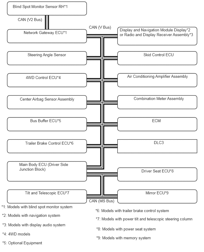

Y195600E01
0.448,0.146 2.781,0.469 2.333,0.323 10 false Blind Spot Monitor Sensor RH*1 0.625,0.604 1.604,0.969 0.979,0.365 10 false CAN (V2 Bus) 3.125,0.875 4.115,1.188 0.99,0.313 10 false CAN (V Bus) 0.833,1.063 2.75,1.448 1.917,0.385 10 false Network Gateway ECU*1 0.969,1.844 2.573,2.167 1.604,0.323 10 false Steering Angle Sensor 0.906,2.646 2.573,2.938 1.667,0.292 10 false 4WD Control ECU*4 0.698,3.406 2.813,3.781 2.115,0.375 10 false Center Airbag Sensor Assembly 4.698,3.385 6.719,3.74 2.021,0.354 10 false Combination Meter Assembly 4.469,2.604 6.823,2.958 2.354,0.354 10 false Air Conditioning Amplifier Assembly 5.042,1.844 6.594,2.198 1.552,0.354 10 false Skid Control ECU 4.208,0.969 6.813,1.552 2.604,0.583 10 false Display and Navigation Module Display*2 or Radio and Display Receiver Assembly*3 5.344,4.167 6.021,4.51 0.677,0.344 10 false ECM 5.406,4.938 6.104,5.323 0.698,0.385 10 false DLC3 4.969,5.938 6.406,6.302 1.438,0.365 10 false Driver Seat ECU*8 5.115,6.708 6.323,7.083 1.208,0.375 10 false Mirror ECU*9 0.875,6.708 2.771,7.094 1.896,0.385 10 false Tilt and Telescopic ECU*7 0.677,5.708 2.51,6.354 1.833,0.646 10 false Main Body ECU (Driver Side Junction Block) 0.885,4.958 2.781,5.333 1.896,0.375 10 false Trailer Brake Control ECU*6 1.063,4.167 2.573,4.51 1.51,0.344 10 false Bus Buffer ECU*5 0.052,7.198 2.865,7.51 2.813,0.313 10 false *1: Models with blind spot monitor system 0.083,7.833 2.823,8.156 2.74,0.323 10 false *3: Models with display audio system 3.125,6.99 4.156,7.333 1.031,0.344 10 false CAN (MS Bus) 0.073,7.5 2.51,7.813 2.438,0.313 10 false *2: Models with navigation system 0.083,8.156 2,8.469 1.917,0.313 10 false *4: 4WD models 0.083,8.469 2.229,8.813 2.146,0.344 10 false *5: Optional Equipment 3.354,7.333 6.292,7.646 2.938,0.313 10 false *6: Models with trailer brake control system 3.365,7.625 7.01,7.958 3.646,0.333 10 false *7: Models with power tilt and telescopic steering column 3.385,8.292 6.292,8.615 2.906,0.323 10 false *9: Models with memory system 3.385,7.979 6.01,8.26 2.625,0.281 10 false *8: Models with power seat system


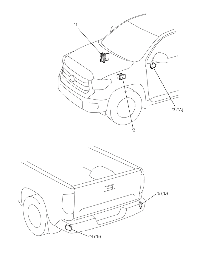
LAYOUT OF MAIN COMPONENTS


Y195601C01
6.135,3.75 5.333,2.302 true 3.615,1.979 2.708,0.969 true 4.646,4.458 4.281,2.698 true 5.438,6.792 4.917,7.156 true 3.094,8.26 2.448,7.99 true 2.583,0.76 2.771,1.01 0.188,0.25 10 false *1 4.594,4.458 4.823,4.688 0.229,0.229 10 false *2 6,3.75 6.604,4.01 0.604,0.26 10 false *3 (*A) 5.469,6.667 6.094,7.021 0.625,0.354 10 false *5 (*B) 3.125,8.177 3.75,8.479 0.625,0.302 10 false *4 (*B)
*A Models with Memory System *B Models with Blind Spot Monitor System
*1 ECM *2 Skid Control ECU
*3 Mirror ECU *4 Blind Spot Monitor Sensor LH
*5 Blind Spot Monitor Sensor RH - -


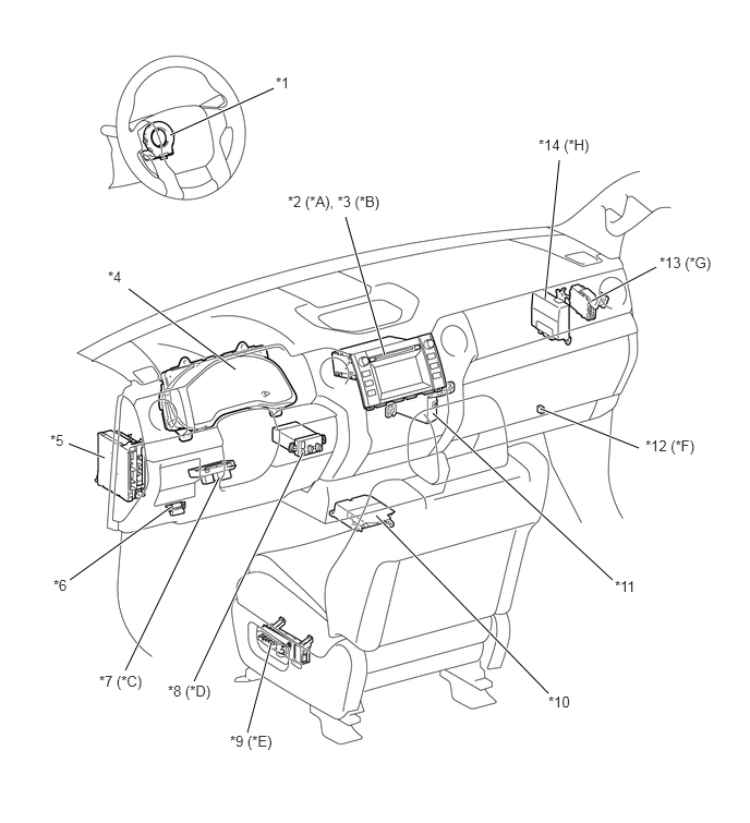
Y195602C01
1.625,1.292 2.615,0.844 true 2.25,3.531 1.229,2.76 true 5.208,2.854 5.344,1.531 true 3.677,3.396 3.302,2.073 true 5.656,2.875 6.271,2.552 true 5.167,3.906 6.104,4.281 true 5.854,5.542 4.135,3.948 true 5.24,6.625 3.594,4.927 true 2.365,7 2.594,6.135 true 1.854,6.51 2.896,4.323 true 1.198,6.406 2.094,4.563 true 0.667,5.542 1.635,4.844 true 0.656,4.24 1,4.375 true 2.635,0.708 2.865,0.99 0.229,0.281 10 false *1 2.75,1.844 3.854,2.104 1.104,0.26 10 false *2 (*A), *3 (*B) 5.146,1.302 5.833,1.552 0.688,0.25 10 false *14 (*H) 6.302,2.427 6.958,2.698 0.656,0.271 10 false *13 (*G) 6.167,4.177 6.865,4.427 0.698,0.25 10 false *12 (*F) 5.875,5.521 6.208,5.771 0.333,0.25 10 false *11 5.24,6.625 5.563,6.906 0.323,0.281 10 false *10 2.198,7 2.865,7.25 0.667,0.25 10 false *9 (*E) 1.604,6.521 2.229,6.792 0.625,0.271 10 false *8 (*D) 0.948,6.427 1.552,6.688 0.604,0.26 10 false *7 (*C) 0.51,5.51 0.729,5.781 0.219,0.271 10 false *6 0.479,4.125 0.688,4.385 0.208,0.26 10 false *5 1.031,2.563 1.24,2.823 0.208,0.26 10 false *4
*A Models with Navigation System *B Models with Display Audio System
*C Models with Power Tilt and Telescopic Steering Column *D Models with Trailer Brake Control System
*E Models with Power Seat System *F Optional Equipment
*G Models with Blind Spot Monitor System *H 4WD Models
*1 Steering Angle Sensor *2 Display and Navigation Module Display
*3 Radio and Display Receiver Assembly *4 Combination Meter Assembly
*5 Main Body ECU (Driver Side Junction Block) *6 DLC3
*7 Tilt and Telescopic ECU *8 Trailer Brake Control ECU
*9 Driver Seat ECU *10 Center Airbag Sensor Assembly
*11 Air Conditioning Amplifier Assembly *12 Bus Buffer ECU
*13 Network Gateway ECU *14 4WD Control ECU


DIAGNOSIS


a.

If a malfunction occurs on the CAN communication bus, ECUs that are connected to the CAN communication bus store the DTC (Diagnostic Trouble Code) in memory.

i.

The 5-digit DTCs can be read after connecting a hand-held tester to DLC3.


ii.

DLC3 is equipped with a CAN-H and a CAN-L terminal on the V bus to allow CAN diagnosis. It is possible to determine if there is an open or short in the main wires of the V bus by measuring the resistance value between these terminals.

HINT:

For details, refer to the Repair Manual.