BODY ELECTRICAL AIR CONDITIONING GENERAL/CONTROL/DETAILS CONSTRUCTION AND OPERATION
Heater Control Panel
An electric heater control panel is used.
The control panel has large switches and knobs, improving ease of use and visibility.
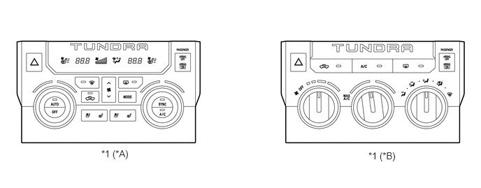
| *A | For Automatic A/C | *B | For Manual A/C |
| *1 | Heater Control Panel | - | - |
Air Conditioning Unit
General
A semi-centrally located air conditioning unit, in which the evaporator and heater core are mounted transversely, is used. As a result, the air conditioning unit is made compact and lightweight.
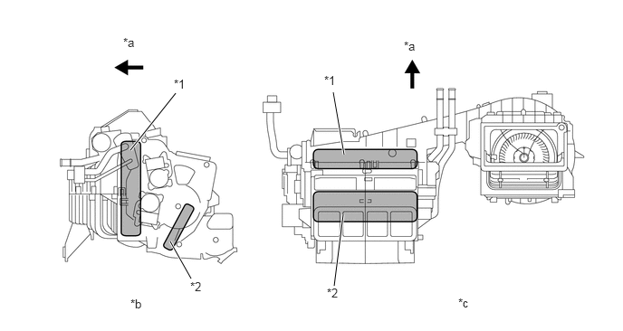
| *1 | Evaporator | *2 | Heater Core |
| *a | Front | *b | Side View |
| *c | Top View | - | - |
Evaporator
An RS (Revolutionary super-slim Structure) type evaporator is used. Placing the tanks at the top and the bottom of the evaporator and adopting a micropore tube construction have realized the following effects:
The heat exchange efficiency is improved.
The temperature distribution is made more uniform.
The evaporator is made thinner. 90 mm (3.5 in.) → 50 mm (2.0 in.)
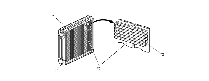
| *1 | Tank | *2 | Micropore Tube |
| *3 | Cooling Fin | - | - |
Evaporator Temperature Sensor
The evaporator temperature sensor detects the temperature of the cool air immediately past the evaporator in the form of resistance changes, and outputs it to the A/C ECU.
Heater Core
A compact, lightweight, and highly efficient SFA (Straight Flow Aluminum)-II type heater core is used.

Blower Motor
The blower motor has a built-in blower controller, and is controlled using duty control performed by the A/C ECU.
BUS Connector
A BUS connector is used in the wire harness connection that connects the servo motor from the A/C ECU.
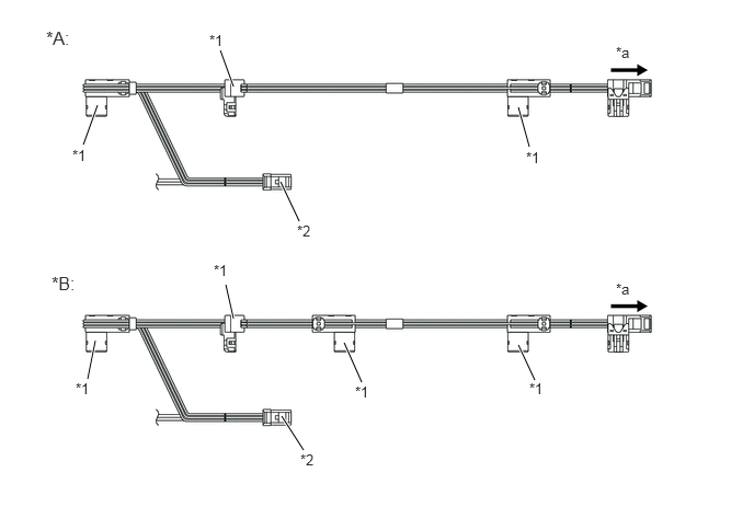
| *A | For Manual A/C | *B | For Automatic A/C |
| *1 | BUS Connector | *2 | Evaporator Temperature Sensor |
| *a | To A/C ECU | - | - |
The BUS connector has a built-in driver IC which communicates with each servo motor connector, actuates the servo motor, and has a position detection function. This enables bus communication for the servo motor wire harness, for a more lightweight construction and a reduced number of wires.
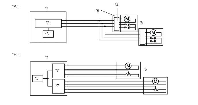
| *A | With BUS Connector | *B | Without BUS Connector |
| *1 | A/C ECU | *2 | Communication IC |
| *3 | CPU | *4 | Communication Driver IC |
| *5 | BUS Connector | *6 | Servo Motor |
| *7 | Drive IC | - | - |
Servo Motor
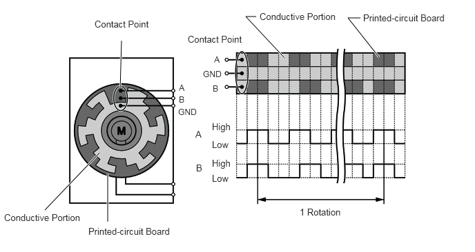
The pulse pattern type servo motor consists of a printed circuit board and a servo motor. The printed circuit board has three contact points, and can transmit two ON-OFF signals to the A/C ECU based on the difference of the pulse phases. The BUS connector can detect the damper position and movement direction with this signal.
Clean Air Filter
A high efficiency type clean air filter is used. This filter excels in the removal of dust and pollen. The filter is made of polyester.
Because the filter is made of polyester, it can be disposed of easily as a non hazardous combustible material, a feature that is provided in consideration of the environment.
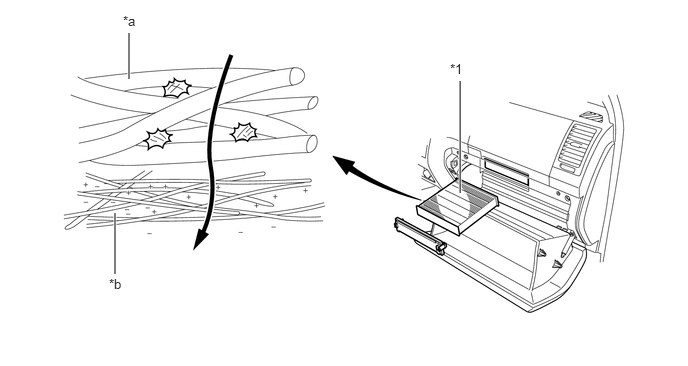
| *1 | Clean Air Filter | - | - |
| *a | Large Foreign Object Filter Layer | *b | Electret Layer |
- HINT:
-
The replacement interval for the clean air filter is 30000 miles. However, observation of these guidelines should depend on the usage conditions (or environment).
Condenser
A MF (Multi-Flow) type condenser is used. The condenser consists of two cooling portions: a condensing portion and a super-cooling portion, and gas-liquid separator (modulator) are integrated together. This condenser uses a sub-cool cycle that offers excellent heat-exchange performance.
In the sub-cool cycle, after the refrigerant passes through the condensing portion of the condenser, both the liquid refrigerant and the gaseous refrigerant that could not be liquefied are cooled again in the super-cooling portion. Thus, the refrigerant is sent to the evaporator in an almost completely liquefied state.
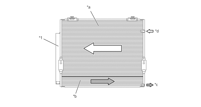
| *1 | Modulator | - | - |
| *a | Condensing Portion | *b | Super-cooling Portion |
| *c | Liquid Refrigerant | *d | Gaseous Refrigerant |
- HINT:
-
The point at which the air bubbles disappear in the refrigerant of the sub-cool cycle is lower than the proper amount of refrigerant with which the system must be filled. Therefore, if the system is recharged with refrigerant based on the point at which the air bubbles disappear, the amount of refrigerant would be insufficient. As a result, the cooling performance of the system would be affected. If the system is overcharged with refrigerant, this will also lead to reduced performance.
-
For the proper method of verifying the amount of the refrigerant and for instructions on how to recharge the system with refrigerant, refer to the Repair Manual.
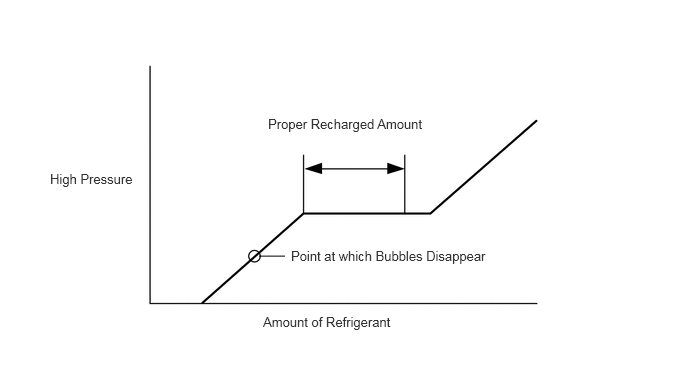 2.698,2.667 2.969,2.667 false 0.521,1.781 1.542,2.135 1.021,0.354 10 false High Pressure 2.792,1.208 4.552,1.604 1.76,0.396 10 false Proper Recharged Amount 3.031,2.583 5.302,2.99 2.271,0.406 10 false Point at which Bubbles Disappear 2.74,3.271 4.188,3.688 1.448,0.417 10 false Amount of Refrigerant
A/C Compressor
A 10S20C type A/C compressor is used. This A/C compressor is a compact, lightweight, and low-noise swash plate type.
This compressor consist of an A/C pulley, shaft, lug plate, swash plate, piston, shoe, crank chamber, cylinder, and lock sensor.
The lock sensor sends an A/C compressor speed signal to the ECM. The ECM compares this signal with an engine speed signal sent from the crankshaft position sensor. If the ECM determines that the A/C pulley has locked, the ECM turns the magnetic clutch off.
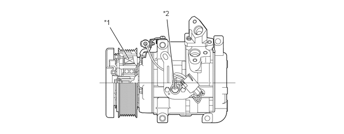
| *1 | Pulley with Magnetic Clutch | *2 | Lock Sensor |
Room Temperature Sensor (Only for Automatic A/C)
The room temperature sensor detects the room temperature based on changes in the resistance of its built-in thermistor. This signal is used by the A/C ECU.
Outside Air Temperature Sensor
The outside temperature sensor detects the outside temperature based on changes in the resistance of its built-in thermistor. This signal is used by the A/C ECU.
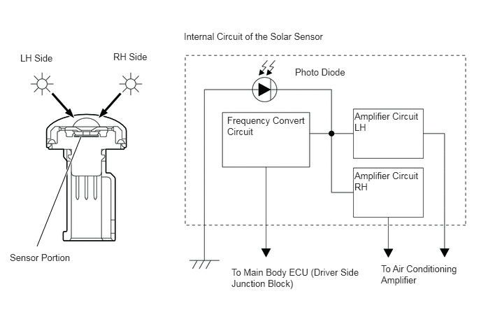
Solar Sensor (Only for Automatic A/C)
The solar sensor consists of a photo diode, two amplifier circuits for the solar sensor, and a frequency converter circuit for the light control sensor.
The solar sensor detects (in the form of changes in the current that flows through the built-in photo diode) the changes in the amount of sunlight from its LH and RH sides (2 directions) and outputs these sunlight strength signals to the A/C ECU.