ENGINE 1UR-FE ENGINE GENERAL/CONTROL/DETAILS ENGINE CONTROL SYSTEM
General
The engine control system of the 1UR-FE engine has the following features:
| System | Outline |
|---|---|
|
*: Models with air conditioning |
|
| Sequential Multiport Fuel Injection (SFI) | ·
An L-type SFI system directly detects the intake air mass using a hot-wire type air flow meter. ·
An independent injection system (in which fuel is injected once into each intake port for each 2 revolutions of the crankshaft) is used. ·
Fuel injection takes 2 forms: ·
Synchronous injection, in which injection always occurs at the same timing relative to the firing order. ·
Non-synchronous injection, in which injection is effected regardless of the crankshaft angle. ·
Synchronous injection is further divided into 2 sub-categories: ·
Group injection, conducted during a cold start. ·
Independent injection, conducted after the engine has started. |
| Electronic Spark Advance (ESA) | ·
Ignition timing is determined by the ECM based on signals from various sensors. The ECM corrects ignition timing in response to engine knocking. ·
This system selects the optimal ignition timing in accordance with the signals received from the sensors and sends the (IGT) ignition signal to the igniter. |
| Electronic Throttle Control System-intelligent (ETCS-i) | Optimally controls the throttle valve opening in accordance with the amount of accelerator pedal effort and the condition of the engine and the vehicle. |
| Dual Variable Valve Timing-intelligent (Dual VVT-i) | Controls the intake and exhaust camshafts to optimal valve timing in accordance with the engine operating conditions. |
| Acoustic Control Induction System (ACIS) | The intake air passages are switched based on engine speed and throttle valve opening angle to provide high performance in all engine speed ranges. |
| EGR Control | Based on the signals received from the various sensors, the ECM determines the EGR volume via EGR valve in accordance with the engine condition. |
| Fuel Pump Control | ·
Based on signals from the ECM, the fuel pump ECU controls the fuel pump in 3 stages. ·
The fuel pump is stopped when the SRS airbag is deployed in a frontal, side, or side rear collision. |
| Air Injection Control | The ECM controls the air injection time based on the signals from the crankshaft position sensor, engine coolant temperature sensor, mass air flow meter and air pressure sensor. |
| Starter Control (Cranking Hold Function) | Once the ignition switch is turned ON while the brake pedal is depressed, this control continues to operate the starter until the engine has started. |
| Air-fuel Ratio Sensor and Heated Oxygen Sensor Heater Control | Maintains the temperature of the air-fuel ratio sensors or heated oxygen sensors at an appropriate level to increase the detection accuracy of the exhaust gas oxygen concentration. |
| Air Conditioning Cut-off Control* | By turning the air conditioning compressor on or off in accordance with the engine condition, driveability is maintained. |
| Evaporative Emission Control | ·
The ECM controls the purge flow of evaporative emission (HC) in the charcoal canister assembly in accordance with the engine conditions. ·
Approximately five hours after the ignition switch has been turned off, the ECM operates the canister pump module to detect any evaporative emission leakage occurring between the fuel tank and the charcoal canister assembly through changes in the fuel tank pressure. |
| Engine Immobiliser | Prohibits fuel delivery and ignition if an attempt is made to start the engine with an invalid key. |
| Brake Override System | The driving torque is restricted when both the accelerator and brake pedals are depressed. (For the Activation Conditions and Inspection Method, refer to the repair manual.) |
| Diagnosis | When the ECM detects a malfunction, the ECM records the malfunction and memorizes information related to the fault. |
| Fail-safe | When the ECM detects a malfunction, the ECM stops or controls the engine in accordance with the data already stored in the memory. |
Construction
The configuration of the engine control system is as shown in the following chart.
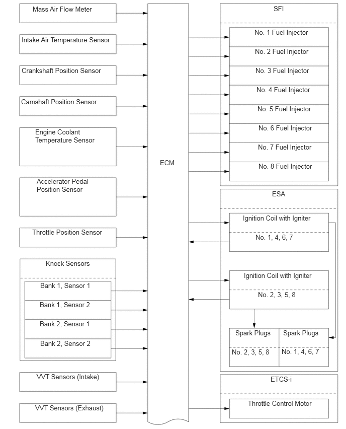
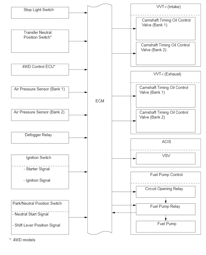
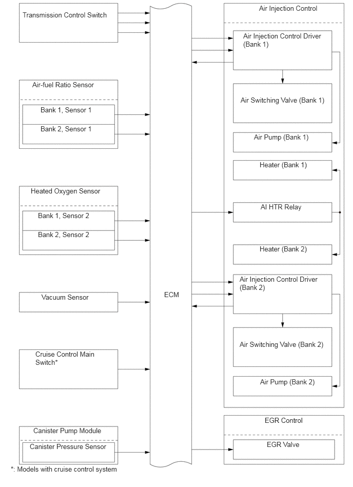
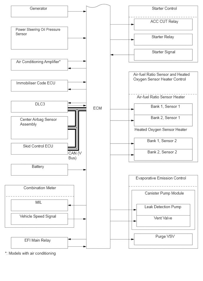
Engine Control System Diagram
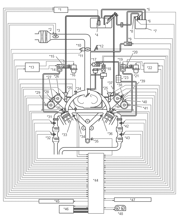
| *1 | Fuel Pump ECU | *2 | Intake Air Temperature Sensor |
| *3 | Mass Air Flow Meter | *4 | Fuel Pump |
| *5 | Vent Valve | *6 | Canister Pump Module |
| *7 | Charcoal Canister Assembly | *8 | Canister Pressure Sensor |
| *9 | Purge VSV | *10 | Throttle Position Sensor |
| *11 | Throttle Control Motor | *12 | Accelerator Pedal Position Sensor |
| *13 | Air Injection Control Driver (Bank 2) | *14 | Air Switching Valve (Bank 2) |
| *15 | Air Pressure Sensor (Bank 2) | *16 | Air Pump (Bank 2) |
| *17 | EGR Valve | *18 | VSV (for ACIS) |
| *19 | Air Switching Valve (Bank 1) | *20 | Air Pressure Sensor (Bank 1) |
| *21 | Air Pump (Bank 1) | *22 | Air Injection Control Driver (Bank 1) |
| *23 | EGR Cooler | *24 | Vacuum Sensor |
| *25 | Fuel Injector | *26 | Intake Camshaft Timing Oil Control Valve (Bank 2) |
| *27 | VVT Sensor (Bank 2, Intake) | *28 | Exhaust Camshaft Timing Oil Control Valve (Bank 2) |
| *29 | VVT Sensor (Bank 2, Exhaust) | *30 | Ignition Coil (with Igniter) |
| *31 | Air-fuel Ratio Sensor (Bank 2, Sensor 1) | *32 | Heated Oxygen Sensor (Bank 2, Sensor 2) |
| *33 | Knock Sensor 1, 2 (Bank 2) | *34 | Engine Coolant Temperature Sensor |
| *35 | Crankshaft Position Sensor | *36 | Knock Sensor 1, 2 (Bank 1) |
| *37 | Intake Camshaft Timing Oil Control Valve (Bank 1) | *38 | Camshaft Position Sensor |
| *39 | VVT Sensor (Bank 1, Intake) | *40 | Exhaust Camshaft Timing Oil Control Valve (Bank 1) |
| *41 | VVT Sensor (Bank 1, Exhaust) | *42 | Air-fuel Ratio Sensor (Bank 1, Sensor 1) |
| *43 | Heated Oxygen Sensor (Bank 1, Sensor 2) | *44 | ECM |
| *45 | Circuit Opening Relay | *46 | DLC3 |
| *47 | Air Conditioning Amplifier | *48 | Combination Meter
·
Vehicle Speed Signal ·
MIL |

|
CAN (V Bus) | - | - |
Layout of Main Components
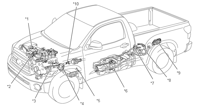
| *1 | Mass Air Flow Meter
·
Intake Air Temp. Sensor |
*2 | Throttle Body
·
Throttle Position Sensor ·
Throttle Control Motor |
| *3 | Air-fuel Ratio Sensor (Bank 2, Sensor 1) | *4 | Air-fuel Ratio Sensor (Bank 1, Sensor 1) |
| *5 | Heated Oxygen Sensor (Bank 1, Sensor 2) | *6 | Fuel Pump Assembly |
| *7 | Canister Pump Module
·
Leak Detection Pump ·
Canister Pressure Sensor ·
Vent Valve |
*8 | Charcoal Canister Assmebly |
| *9 | Fuel Pump ECU | *10 | Heated Oxygen Sensor (Bank 2, Sensor 2) |
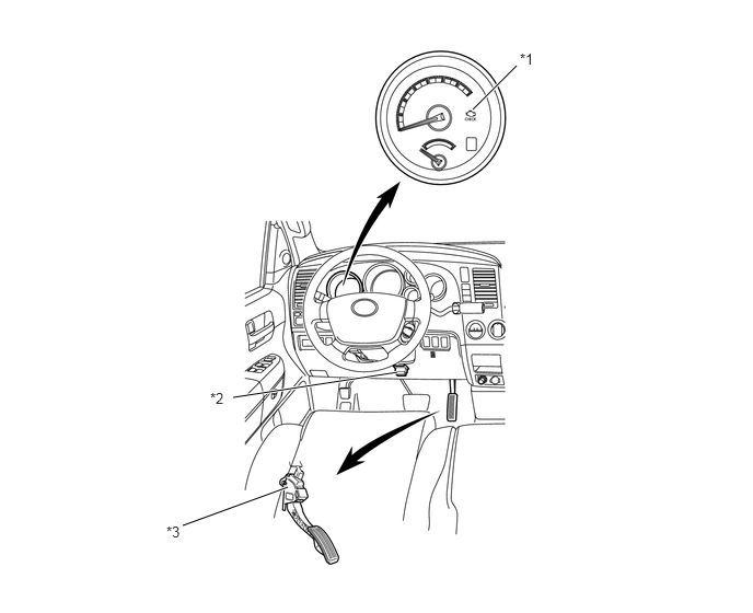
| *1 | MIL | *2 | DLC3 |
| *3 | Accelerator Pedal Position Sensor | - | - |
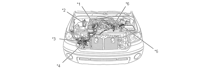
| *1 | Air Switching Valve (Bank 2)
·
Air Pressure Sensor |
*2 | ECM |
| *3 | Air Pump (Bank 2) | *4 | Air Pump (Bank 1) |
| *5 | Air Injection Control Driver | *6 | Air Switching Valve (Bank 1)
·
Air Pressure Sensor |
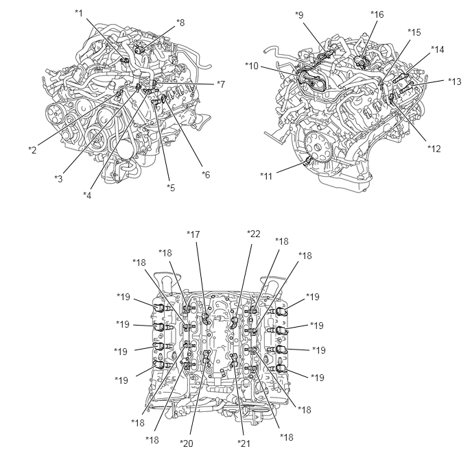
| *1 | Vacuum Sensor | *2 | Engine Coolant Temperature Sensor |
| *3 | Camshaft Position Sensor | *4 | Camshaft Timing Oil Control Valve (Bank 1, Intake) |
| *5 | Camshaft Timing Oil Control Valve (Bank 1, Exhaust) | *6 | VVT Sensor (Bank 1, Exhaust) |
| *7 | VVT Sensor (Bank 1, Intake) | *8 | Purge VSV |
| *9 | VSV (for ACIS) | *10 | ACIS Actuator |
| *11 | Crankshaft Position Sensor | *12 | VVT Sensor (Bank 2, Exhaust) |
| *13 | Camshaft Timing Oil Control Valve (Bank 2, Exhaust) | *14 | Camshaft Timing Oil Control Valve (Bank 2, Intake) |
| *15 | VVT Sensor (Bank 2, Intake) | *16 | EGR Valve |
| *17 | Knock Sensor 2 (Bank 2) | *18 | Fuel Injector |
| *19 | Ignition Coil (with Igniter) | *20 | Knock Sensor 1 (Bank 2) |
| *21 | Knock Sensor 1 (Bank 1) | *22 | Knock Sensor 2 (Bank 1) |
Main Components of Engine Control System
General
The main components of the 1UR-FE engine control system are as follows:
| Components | Outline | Quantity | Function |
|---|---|---|---|
| ECM | 32-bit CPU | 1 | The ECM optimally controls the SFI, ESA and ISC to suit the operating conditions of the engine in accordance with the signals provided by the sensors. |
| Mass Air Flow Meter | Hot-wire Type | 1 | This sensor has a built-in hot-wire to directly detect the intake air mass and flow rate. |
| Intake Air Temperature Sensor | Thermistor Type | 1 | This sensor detects the intake air temperature by means of an internal thermistor. |
| Accelerator Pedal Position Sensor | Hall IC Type (Non-contact Type) | 1 | This sensor detects the amount of pedal effort applied to the accelerator pedal. |
| Throttle Position Sensor | Hall IC Type (Non-contact Type) | 1 | This sensor detects the throttle valve opening angle. |
| Crankshaft Position Sensor | MRE Type (Rotor Teeth/36-2) | 1 | This sensor detects the engine speed and the crankshaft position. |
| Camshaft Position Sensor | MRE Type (Rotor Teeth/3) | 1 | This sensor detects the camshaft position and performs the cylinder identification. |
| VVT Sensor (Intake) | MRE Type (Rotor Teeth/3) | 1 each bank | This sensor detects the actual valve timing. |
| VVT Sensor (Exhaust) | MRE Type (Rotor Teeth/3) | 1 each bank | This sensor detects the actual valve timing. |
| Knock Sensor | Built-in Piezoelectric Element (Flat Type) | 2 each bank | This sensor detects an occurrence of the engine knocking indirectly from the vibration of the cylinder block caused by the occurrence of engine knocking. |
| Heated Oxygen Sensor | Cup Type with Heater | 1 each bank | This sensor detects the oxygen concentration in the exhaust emission by measuring the electromotive force generated in the sensor itself. |
| Air-fuel Ratio Sensor | Planar Type with Heater | 1 each bank | As with the heated oxygen sensor, this sensor detects the oxygen concentration in the exhaust emissions. However, it detects the oxygen concentration in the exhaust emissions linearly. |
| Vacuum Sensor | Semiconductor Silicon Chip Type | 1 | This sensor uses built-in semiconductors to detect the intake manifold pressure. |
| Engine Coolant Temperature Sensor | Thermistor Type | 1 | This sensor detects the engine coolant temperature by means of an internal thermistor. |
| Fuel Injector | 12-hole Type | 8 | This fuel injector contains an electromagnetically operated nozzle to inject fuel into the intake port. |
| Camshaft Timing Oil Control Valve | Electromagnetic Coil Type | 2 each bank | The camshaft timing oil control valve changes the valve timing by switching the oil passage that acts on the VVT-i controller in accordance with the signals received from the ECM. |
Mass Air Flow Meter
This mass air flow meter, which is a slot-in type, allows a portion of the intake air to flow through the detection area. By directly measuring the mass and the flow rate of the intake air, the detection precision is improved and the intake air resistance is reduced.
This mass air flow meter has a built-in intake air temperature sensor.
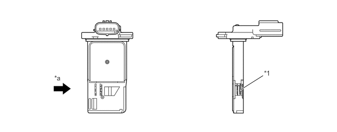
| *1 | Intake Air Temperature Sensor | - | - |
| *a | Air Flow | - | - |
Knock Sensor (Flat Type)
General
In the conventional type knock sensor (resonant type), a vibration plate which has the same resonance point as the knocking frequency of the engine is built in and can detect the vibration in this frequency band.
However, a flat type knock sensor (non-resonant type) has the ability to detect vibration in a wider frequency band from approximately 6 kHz to 15 kHz, and has the following feature:
The engine knocking frequency will change a little depending on the engine speed. The flat type knock sensor can detect the vibration even when the engine knocking frequency is changed. Thus the vibration detection ability has been increased compared to the conventional type knock sensor, and more precise ignition timing control has been made possible.
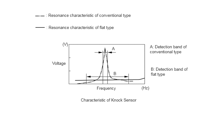
Construction
The flat type knock sensor is installed on the engine through the stud bolt installed on the cylinder block. For this reason, a hole for the stud bolt runs through the center of the sensor.
Inside of the sensor, a steel weight is located on the upper portion and a piezoelectric element is located under the weight through the insulator.
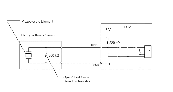
The open/short circuit detection resistor is integrated.
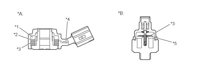
| *A | Flat Type Knock Sensor (Non-resonant Type) | *B | Conventional Type Knock Sensor (Resonant Type) |
| *1 | Steel Weight | *2 | Insulator |
| *3 | Piezoelectric Element | *4 | Open/Short Circuit Detection Resistor |
| *5 | Vibration Plate | - | - |
Operation
The knocking vibration is transmitted to the steel weight and its inertia applies pressure to the piezoelectric element. This action generates electromotive force.
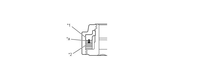
| *1 | Steel Weight | *2 | Piezoelectric Element |
| *a | Inertia | - | - |
Open/Short Circuit Detection Resistor
While the ignition is ON, the open/short circuit detection resistor in the knock sensor and the resistor in the ECM keep the voltage at terminal KNK1 of the engine constant.
An Integrated Circuit (IC) in the ECM constantly monitors the voltage of terminal KNK1. If the open/short circuit occurs between the knock sensor and the ECM, the voltage of terminal KNK1 will change and the ECM will detect the open/short circuit and store a Diagnostic Trouble Code (DTC).
- HINT:
-
These knock sensors are mounted in specific directions at specific angles. To prevent the right and left bank wiring connectors from being interchanged, be sure to install each sensor in its prescribed direction. For details, refer to the Repair Manual.
Vacuum Sensor
The vacuum sensor consists of a silicon chip that changes its electrical resistance when pressure is applied to it. The sensor converts the pressure into an electrical signal, and sends it to the ECM in an amplified form.
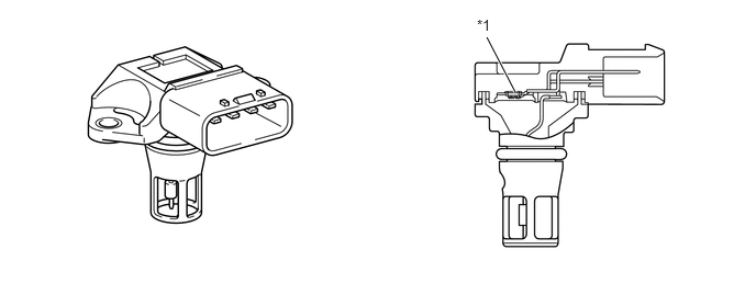
| *1 | Silicon Chip | - | - |
Air-fuel Ratio Sensor and Heated Oxygen Sensor
General
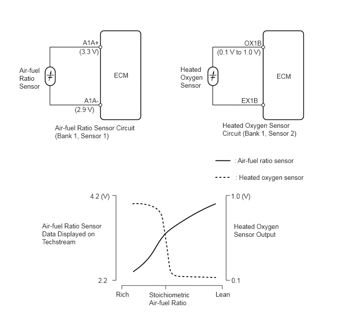
The heated oxygen sensor and the air-fuel ratio sensor differ in output characteristics.
The output voltage of the heated oxygen sensor changes in accordance with the oxygen concentration in the exhaust gas. The ECM uses this output voltage to determine whether the present air-fuel ratio is richer or leaner than the stoichiometric air-fuel ratio.
Approximately 0.4 V is constantly applied to the air-fuel ratio sensor, which outputs an amperage that varies in accordance with the oxygen concentration in the exhaust gas. The ECM uses this output voltage to determine whether the present air-fuel ratio is richer or leaner than the stoichiometric air-fuel ratio. The air-fuel ratio sensor data is read out by the Techstream.
Construction
The basic construction of the heated oxygen sensor and the air-fuel ratio sensor is the same. However, they are divided into the cup type and the planar type, according to the different types of heater construction that are used.
The cup type sensor contains a sensor element that surrounds the heater.
The planar type sensor uses alumina, which excels in heat conductivity and insulation, to integrate a sensor element with the heater, thus improving the warm-up performance of the sensor.
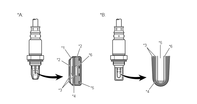
| *A | Air-fuel Ratio Sensor (Planar Type) | *B | Heated Oxygen Sensor (Cup Type) |
| *1 | Diffusion Resistance Layer | *2 | Alumina |
| *3 | Platinum Electrode | *4 | Sensor Element (Zirconia) |
| *5 | Heater | *6 | Atmosphere |
| Sensor Type | Planar Type | Cup Type |
| Warm-up Time | Approx. 10 sec. | Approx. 30 sec. |
Crankshaft Position Sensor, Camshaft Position Sensor and VVT Sensor
General
Magnetic Resistance Element (MRE) sensors are used for the crankshaft position, camshaft position, and VVT sensors.
The timing rotor for the crankshaft position sensor is installed on the back end of the crankshaft. The timing rotor has 34 teeth, with 2 teeth missing, at 10° intervals. Based on these teeth, the crankshaft position sensor transmits crankshaft position signals (NE signal) consisting of 33 high and low output pulses every 10° per revolution of the crankshaft, and 1 high and low output pulse every 30°. The ECM uses the NE signal for detecting the crankshaft position as well as for detecting the engine speed. It uses the missing teeth signal to determine the top dead center.
The camshaft position sensor uses a timing rotor installed on the front end of the intake camshaft sprocket of the left bank. Based on the timing rotor, the sensor outputs camshaft position signals (G2 signal) consisting of 3 (3 high output, 3 low output) pulses for every 2 revolutions of the crankshaft. The ECM compares the G2 and NE signals to detect the camshaft position and identify the cylinder.
The VVT sensors (intake and exhaust) use timing rotors installed on the intake and exhaust camshafts of each bank. Based on the timing rotors, the sensors output VVT position signals consisting of 3 (3 high output, 3 low output) pulses for every 2 revolutions of the crankshaft. The ECM compares these VVT position signals and the NE signal to detect the actual valve timing.
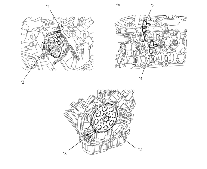
| *1 | Camshaft Position Sensor | *2 | Timing Rotor |
| *3 | VVT Sensor (Intake) | *4 | VVT Sensor (Exhaust) |
| *5 | Crankshaft Position Sensor | - | - |
| *a | Bank 1 | - | - |
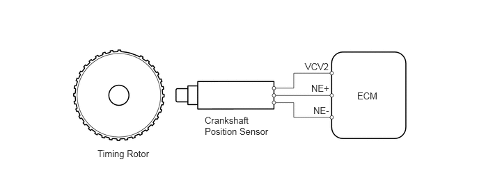
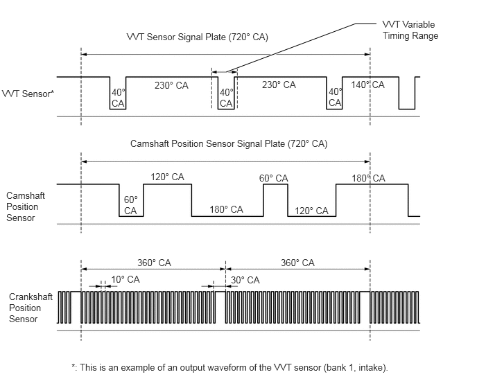
MRE Type Sensor
The MRE type sensor consists of an MRE, a magnet and a sensor.
The direction of the magnetic field changes due to the profile (protruding and non-protruding portions) of the timing rotor, which passes by the sensor. As a result, the resistance of the MRE changes, and the output voltage to the ECM changes to high or low. The ECM detects the crankshaft and camshaft positions based on this output voltage.
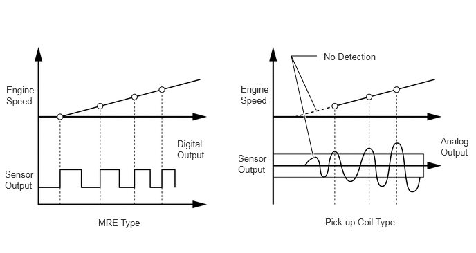
The differences between the MRE type sensor and the pick-up coil type sensor used on the conventional models are as follows:
The MRE type sensor outputs a constant level of high and low digital signals regardless of the engine speed. Therefore, the MRE type sensor can detect the positions of the crankshaft and camshaft at an early stage of cranking.
The pick-up coil type sensor outputs analog signals with levels that change with the engine speed.
Accelerator Pedal Position Sensor
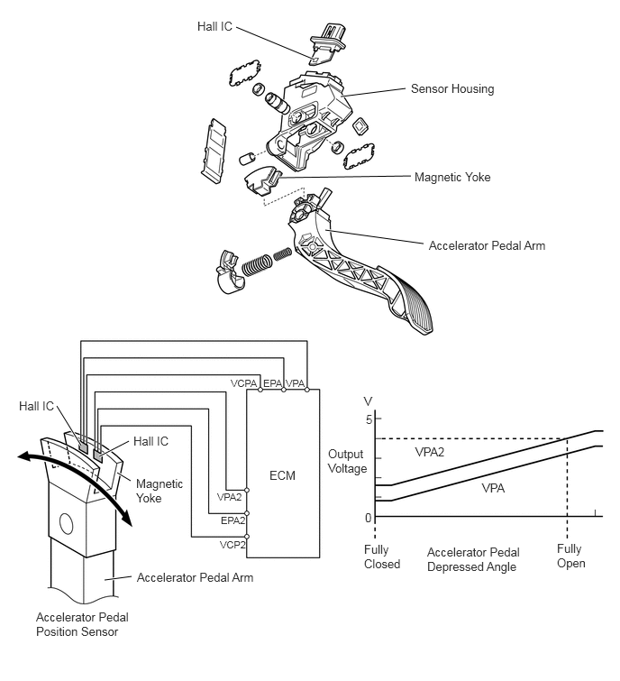
The non-contact type accelerator pedal position sensor uses a Hall IC, which is mounted on the accelerator pedal arm.
The magnetic yoke mounted at the base of the accelerator pedal arm moves around the Hall IC in accordance with the amount of effort applied to the accelerator pedal. The Hall IC converts the changes in the magnetic flux that occur into electrical signals, and outputs them in the form of accelerator pedal position signals to the ECM.
This accelerator pedal position sensor includes 2 Hall ICs and circuits for the main and sub signals. It converts the accelerator pedal depression angles into 2 electric signals with differing characteristics and outputs them to the ECM.
Throttle Position Sensor
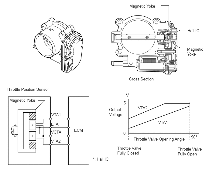
The non-contact type throttle position sensor is mounted on the throttle body, and it uses a Hall IC.
The Hall IC is surrounded by a magnetic yoke. The Hall IC converts the changes that occur in the magnetic flux into electrical signals, and outputs them in the form of throttle valve position signals to the ECM.
The Hall IC contains circuits for the main and sub signals. It converts the throttle valve opening angle into 2 electrical signals that have differing characteristics and outputs them to the ECM.
Electronic Throttle Control System-intelligent (ETCS-i)
General
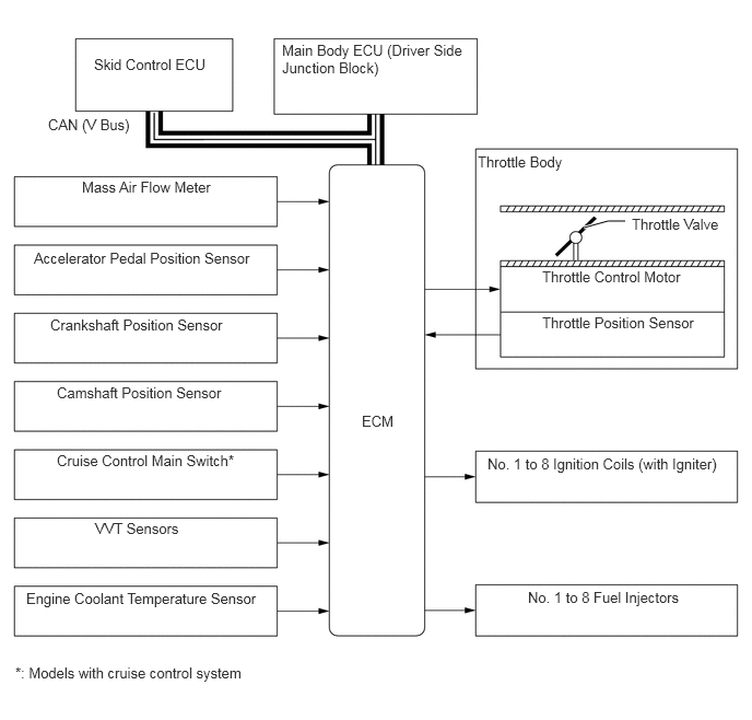
In the conventional throttle body, the throttle valve angle is determined invariably by the amount of accelerator pedal effort. In contrast, ETCS-i uses the ECM to calculate the optimal throttle valve angle that is appropriate for the respective driving condition and uses a throttle control motor to control the angle.
In case of an abnormal condition, this system transfers to the fail-safe mode.
Control
General
The ETCS-i consists of the following functions:
Normal Throttle Control (Non-linear Control)
Idle Speed Control (ISC)
Traction Control (TRAC)/Active Traction Control (A-TRAC)*
*: 4WD models
Vehicle Stability Control (VSC) Coordination Control
Cruise Control*
*: Models with cruise control system
Normal Throttle Control (Non-linear Control)
This control optimizes the throttle valve angle to an angle that is appropriate for driving conditions such as the amount of accelerator pedal effort and the engine speed, in order to achieve excellent throttle control and comfort in all operating ranges.
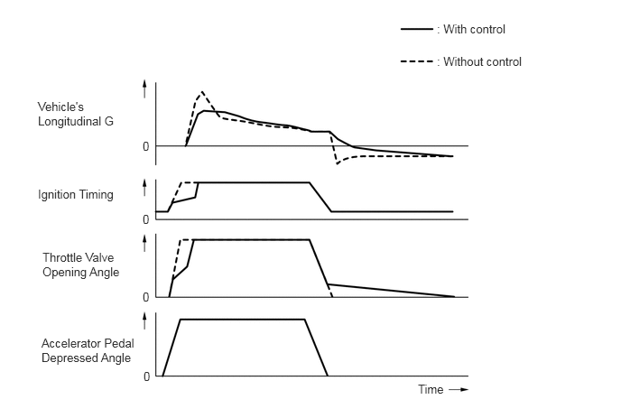
Idle Speed Control
The ECM controls the throttle valve in order to constantly maintain an ideal idle speed.
TRAC/A-TRAC*
*: 4WD models
As part of the A-TRAC, the throttle valve opening angle is reduced by a demand signal sent from the skid control ECU to the ECM. This demand signal is sent if an excessive amount of slippage occurs at a drive wheel, thus ensuring vehicle stability and applying an appropriate amount of power to the road.
VSC Coordination Control
In order to bring the effectiveness of the VSC into full play, the throttle valve angle is regulated through a coordination control by the skid control ECU and the ECM.
Cruise Control*
*: Models with cruise control system
The ECM directly actuates the throttle valve for operation of the cruise control.
Fail-safe Operation due to Accelerator Pedal Position Sensor Trouble
The accelerator pedal position sensor is comprised of 2 (main, sub) sensor circuits.
If a malfunction occurs in either of the sensor circuits, the ECM detects the abnormal signal voltage difference between these two sensor circuits and switches into a fail-safe mode. In this fail-safe mode, the remaining circuit is used to calculate the accelerator pedal opening, in order to operate the vehicle under fail-safe mode control.
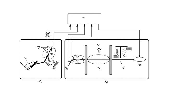
| *1 | ECM | *2 | Accelerator Pedal Position Sensor |
| *3 | Accelerator Pedal | *4 | Throttle Body |
| *5 | Throttle Position Sensor | *6 | Throttle Valve |
| *7 | Return Spring | *8 | Throttle Control Motor |
| *a | Main | *b | Sub |
| *c | Open | - | - |
If both circuits malfunction, the ECM detects the abnormal signal voltage from these two sensor circuits and discontinues the throttle control. At this time, the vehicle can be driven within its idling range.
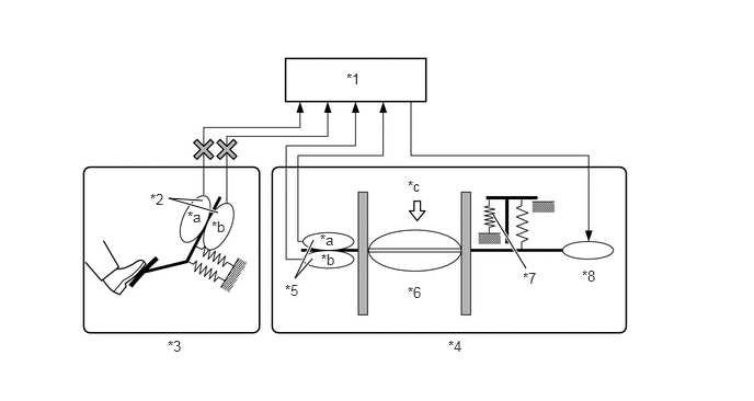
| *1 | ECM | *2 | Accelerator Pedal Position Sensor |
| *3 | Accelerator Pedal | *4 | Throttle Body |
| *5 | Throttle Position Sensor | *6 | Throttle Valve |
| *7 | Return Spring | *8 | Throttle Control Motor |
| *a | Main | *b | Sub |
| *c | Close by Return Spring | - | - |
Fail-safe Operation Caused by Throttle Position Sensor Trouble
The throttle position sensor is comprised of 2 (main, sub) sensor circuits.
If a malfunction occurs in either of the sensor circuits, the ECM detects the abnormal signal voltage difference between these 2 sensor circuits, cuts off the current to the throttle control motor, and switches to a fail-safe mode.
Then, the force of the return spring causes the throttle valve to return and stay at the prescribed base opening position. At this time, the vehicle can be driven in the fail-safe mode while the engine output is regulated through control of the fuel injection and ignition timing in accordance with the accelerator pedal position.
The same control as above is effected if the ECM detects a malfunction in the throttle control motor system.
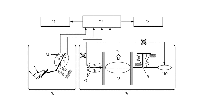
| *1 | Fuel Injector | *2 | ECM |
| *3 | Ignition Coil | *4 | Accelerator Pedal Position Sensor |
| *5 | Accelerator Pedal | *6 | Throttle Body |
| *7 | Throttle Position Sensor | *8 | Throttle Valve |
| *9 | Return Spring | *10 | Throttle Control Motor |
| *a | Main | *b | Sub |
| *c | Return to Prescribed Angle | - | - |
Dual Variable Valve Timing-intelligent (Dual VVT-i) System
General
The Dual VVT-i system is designed to control the intake and exhaust camshafts within a range of 40° and 32° respectively (of crankshaft angle) to provide valve timing optimally suited to the engine operating conditions. This improves torque in all the speed ranges as well as increasing fuel economy and reducing exhaust emissions.
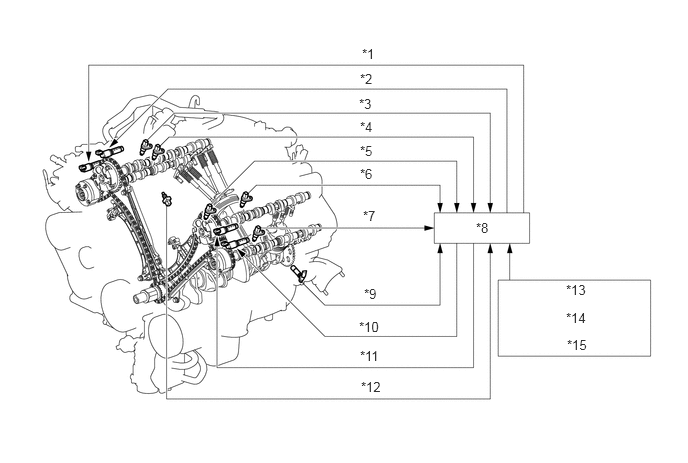
| *1 | Camshaft Timing Oil Control Valve (Bank 2, Exhaust) | *2 | Camshaft Timing Oil Control Valve (Bank 2, Intake) |
| *3 | VVT Sensor (Bank 2, Exhaust) | *4 | VVT Sensor (Bank 2, Intake) |
| *5 | Camshaft Position Sensor | *6 | VVT Sensor (Bank 1, Intake) |
| *7 | VVT Sensor (Bank 1, Exhaust) | *8 | ECM |
| *9 | Crankshaft Position Sensor | *10 | Camshaft Timing Oil Control Valve (Bank 1, Exhaust) |
| *11 | Camshaft Timing Oil Control Valve (Bank 1, Intake) | *12 | Engine Coolant Temperature Sensor |
| *13 | Mass Air Flow Meter | *14 | Throttle Position Sensor |
| *15 | Vehicle Speed Signal | - | - |
By using the engine speed, intake air mass, throttle position and engine coolant temperature, the ECM calculates the optimal valve timing for each driving condition and controls the camshaft timing oil control valves. In addition, the ECM uses signals from the intake and exhaust VVT sensors for each bank and the crankshaft position sensor to detect the actual valve timing, thus providing feedback control to achieve the target valve timing.
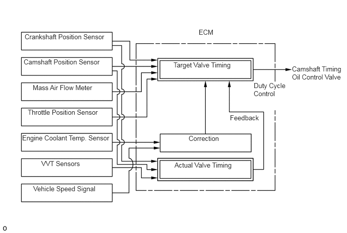
Effectiveness of Dual VVT-i System
| Condition | Operation | Timing/Position | Objective | Effect | |
|---|---|---|---|---|---|
| During Idling | 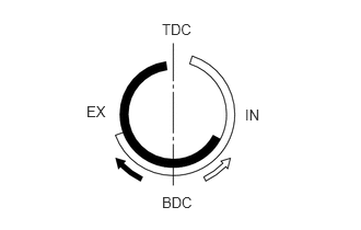
1.542,0.198 2,0.396
0.458,0.198
10
false
TDC
0.823,0.979 1.281,1.177
0.458,0.198
10
false
EX
2.333,1.01 2.792,1.208
0.458,0.198
10
false
IN
1.542,1.844 2,2.042
0.458,0.198
10
false
BDC
|
IN | Most Retarded Position | Eliminating overlap to reduce blow back to the intake side. | ·
Stabilized idle speed ·
Better fuel economy |
| EX | Most Advanced Position | ||||
| In Low Speed Range with Light to Medium Load | 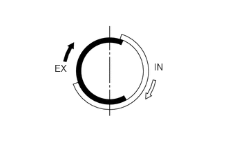
0.823,0.948 1.135,1.146
0.313,0.198
10
false
EX
2.323,0.927 2.635,1.125
0.313,0.198
10
false
IN
|
IN | Retarded | Retarding the intake valve close timing and reducing pumping loss. Increasing overlap and internal EGR. | ·
Better fuel economy ·
Improved emission control |
| EX | Retarded | ||||
| In Low to Medium Speed Range with Heavy Load | 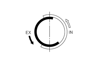
2.292,1 2.604,1.198
0.313,0.198
10
false
IN
0.854,1.01 1.167,1.208
0.313,0.198
10
false
EX
|
IN | Advanced | Advancing the intake valve close timing, reducing intake air blow back to the intake side, and improving volumetric efficiency. | Improved torque in low to medium speed range |
| EX | Advanced | ||||
| In High Speed Range with Heavy Load | 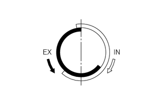
0.875,0.979 1.188,1.177
0.313,0.198
10
false
EX
2.323,0.979 2.635,1.177
0.313,0.198
10
false
IN
|
IN | Retarded | Retarding the intake valve close timing and improving volumetric efficiency using the inertia force of the intake air. | Improved output |
| EX | Advanced | ||||
| At Low Temperatures | 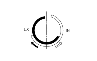
2.333,1.01 2.646,1.208
0.313,0.198
10
false
IN
0.844,0.969 1.156,1.167
0.313,0.198
10
false
EX
|
IN | Most Retarded Position | Eliminating overlap to reduce blow back to the intake side. Fixing valve timing at extremely low temperatures and increasing the control range as the temperature rises. | ·
Stabilized fast idle speed ·
Better fuel economy |
| EX | Most Advanced Position | ||||
·
Upon Starting ·
Stopping Engine |
2.333,1.01 2.646,1.208
0.313,0.198
10
false
IN
0.844,0.969 1.156,1.167
0.313,0.198
10
false
EX
|
IN | Most Retarded Position | Controlling valve timing and fixing it to the optimal timing for engine start. | Improved startability |
| EX | Most Advanced Position | ||||
Construction
VVT-i Controller
This controller consists of an outer housing driven by the timing chain sprocket, and a vane coupled to each camshaft.
The intake side uses a VVT-i controller with 3 vanes, and the exhaust side uses one with 4 vanes.
When the engine stops, the intake side VVT-i controller is locked at the most retarded angle by its lock pin, and the exhaust side controller is locked at the most advanced angle. This ensures excellent engine startability.
The oil pressure sent from the advance or retard side passages of the intake and exhaust camshafts causes rotation of the VVT-i controller vane sub-assembly relative to the timing chain sprocket, to vary the valve timing continuously.
An advance assist spring is provided on the exhaust side VVT-i controller. This helps to apply torque in the advanced angle direction so that the vane lock pin securely engages with the housing when the engine stops.
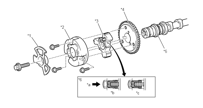
| *1 | Timing Rotor | *2 | Outer Housing |
| *3 | Vane (Coupled to Intake Camshaft) | *4 | Timing Chain Sprocket |
| *5 | Intake Camshaft | *6 | Lock Pin |
| *a | Oil Pressure | *b | Engine Operating |
| *c | Engine Stopped | - | - |
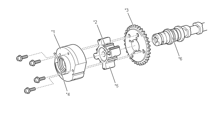
| *1 | Outer Housing | *2 | Lock Pin |
| *3 | Timing Chain Sprocket | *4 | Advanced Assist Spring |
| *5 | Vane (Fixed on Exhaust Camshaft) | *6 | Exhaust Camshaft |
Camshaft Timing Oil Control Valve
This camshaft timing oil control valve controls the spool valve using duty cycle control from the ECM. This allows hydraulic pressure to be applied to the VVT-i controller advance or retard side. When the engine is stopped, the camshaft timing oil control valve (intake) will move to the retard position, and the camshaft timing oil control valve (exhaust) will move to the advance position.
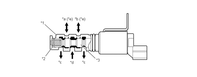
| *1 | Sleeve | *2 | Spring |
| *3 | Spool Valve | - | - |
| *a | To VVT-i Controller (Advance Side) | *b | To VVT-i Controller (Retard Side) |
| *c | Drain | *d | Oil Pressure |
| *e | On the exhaust side oil control valve, the advance and retard sides are reversed. | - | - |
Operation
Advance
When the camshaft timing oil control valve is positioned as illustrated below by the advance signals from the ECM, the resultant oil pressure is applied to the timing advance side vane chamber to rotate the camshaft in the timing advance direction.
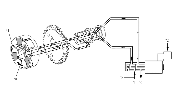
| *1 | Vane | *2 | ECM |
| *a | Rotation Direction | *b | Oil Pressure |
| *c | In | *d | Drain |
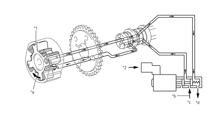
| *1 | Vane | *2 | ECM |
| *a | Rotation Direction | *b | Oil Pressure |
| *c | In | *d | Drain |
Retard
When the camshaft timing oil control valve is positioned as illustrated below by the retard signals from the ECM, the resultant oil pressure is applied to the timing retard side vane chamber to rotate the camshaft in the timing retard direction.
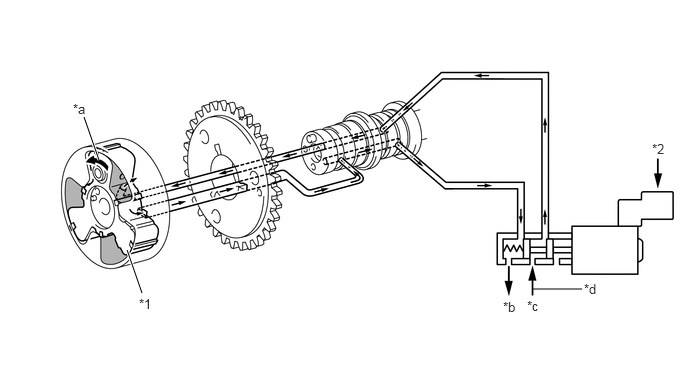
| *1 | Vane | *2 | ECM |
| *a | Rotation Direction | *b | Drain |
| *c | In | *d | Oil Pressure |
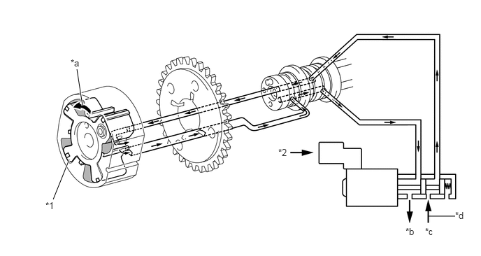
| *1 | Vane | *2 | ECM |
| *a | Rotation Direction | *b | Drain |
| *c | In | *d | Oil Pressure |
Hold
After reaching the target timing, the engine valve timing is maintained by keeping the camshaft timing oil control valve in the neutral position unless the engine operating conditions change.
This maintains the engine valve timing at the desired target position by preventing the engine oil from running out of the oil control valve.
Acoustic Control Induction System (ACIS)
General
The ACIS is implemented by using a bulkhead to divide the intake manifold into 2 stages, with an intake air control valve in the bulkhead being opened and closed to vary the effective length of the intake manifold in accordance with the engine speed and throttle valve opening angle. This increases the power output in all ranges from low to high speed.
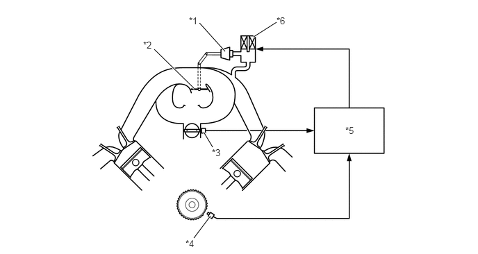
| *1 | ACIS Actuator | *2 | Intake Air Control Valve |
| *3 | Throttle Position Sensor | *4 | Crankshaft Position Sensor |
| *5 | ECM | *6 | VSV (for ACIS) |
Intake Air Control Valve and ACIS Actuator
The intake air control valve and ACIS actuator are integrated with the intake manifold. This valve opens and closes to change the effective length of the intake manifold in 2 stages.

| *1 | Intake Air Control Valve | *2 | ACIS Actuator |
Operation
When Intake Control Valve Closes (VSV On)
The ECM activates the VSV so that the negative pressure acts on the diaphragm chamber of the actuator. This closes the control valve to match the longer pulsation cycle. As a result, the effective length of the intake manifold is lengthened and the intake efficiency in the low-to-medium engine speed range under heavy load and low-to-high engine speed range under low load is improved due to the dynamic effect of the intake air, thereby increasing the power output.
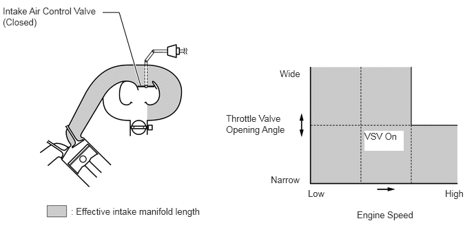
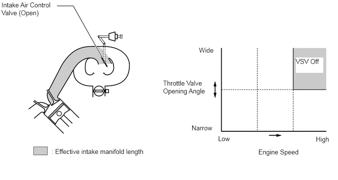
When Intake Control Valve Opens (VSV Off)
The ECM deactivates the VSV so that atmospheric air is led into the diaphragm chamber of the actuator. This opens the control valve to match the shorter pulsation cycle. When the control valve is open, the effective length of the intake manifold is shortened and peak intake efficiency is shifted. This benefits the high engine speed range under heavy load, thus providing greater output at high engine speeds.
EGR Control
The ECM determines the engine condition based primarily on various sensors. The ECM controls the EGR valve to regulate the amount of the EGR gas. This control does not operate when the engine is cold.
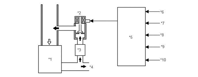
| *1 | Engine | *2 | EGR Valve |
| *3 | EGR Cooler | *4 | Exhaust Pipe |
| *5 | ECM | *6 | Crankshaft Position Sensor (Engine Speed) |
| *7 | Accelerator Pedal Position Sensor | *8 | Vacuum Sensor |
| *9 | Engine Coolant Temperature Sensor | *10 | Mass Air Flow Meter |
Fuel Pump Control
General
In this vehicle, there are 2 types of fuel pump controls. The fuel pump is controlled to an optimum speed to match the engine operating conditions, and the fuel pump operation is stopped when the SRS airbags deploy.
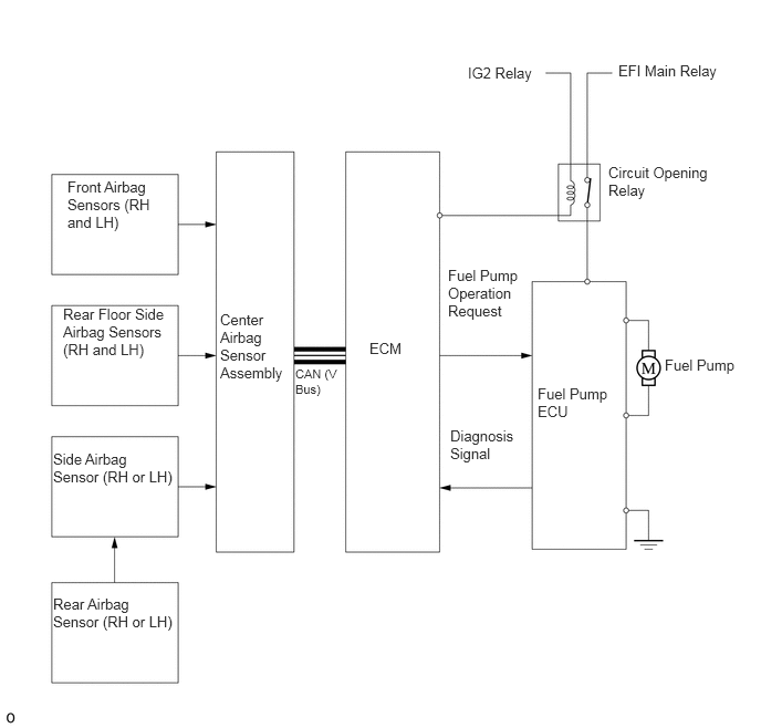
The ECM transmits a fuel pump operation request signal to the fuel pump ECU that corresponds to the engine operating conditions. The fuel pump ECU receives this request signal and controls the speed of the fuel pump in 3 stages. As a result, under light engine loads, fuel pump speed is kept low to reduce electric power loss.
A fuel cut control is used to stop the fuel pump when any of the SRS airbags deploys. In this control, if an airbag deployment signal from the center airbag sensor assembly is detected by the ECM, the ECM will turn off the circuit opening relay. As a result, the power supply to the fuel pump ECU is stopped, causing the fuel pump to stop operating. After the fuel cut control has been activated, turning the ignition switch from off to on cancels the fuel cut control, and the engine can be restarted.
Fuel Pump ECU
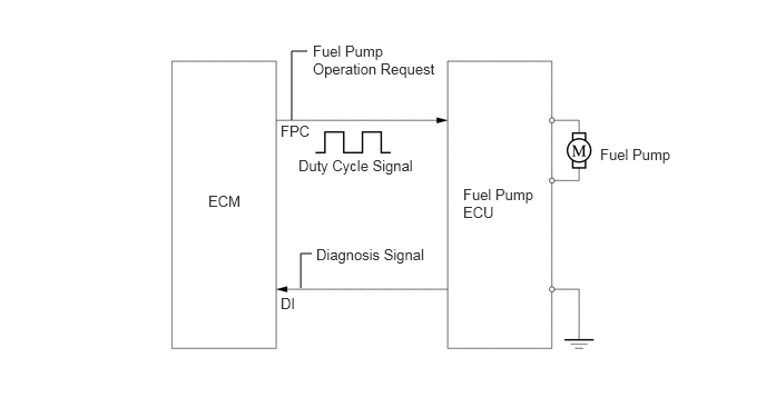
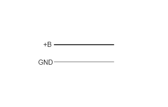
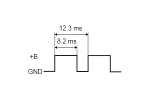
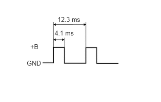
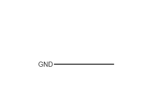
The fuel pump ECU controls fuel pump speed by receiving a duty cycle signal (FPC terminal input) from the ECM, and control is performed in 3 stages.
The fuel pump ECU also detects failures in the input and output circuits at the fuel pump ECU and transmits the failure status to the ECM.
| FPC Input Signal (Duty Cycle Signal) | Fuel Pump Speed |
|---|---|
0.885,0.823 1.094,1.146
0.208,0.323
10
false
+B
0.781,1.188 1.104,1.563
0.323,0.375
10
false
GND
|
High |
0.615,1.094 0.833,1.396
0.219,0.302
10
false
+B
0.583,1.406 0.906,1.698
0.323,0.292
10
false
GND
1.229,0.5 1.854,0.708
0.625,0.208
10
false
12.3 ms
1.188,0.771 1.625,0.99
0.438,0.219
10
false
8.2 ms
|
Middle |
0.646,0.917 0.958,1.115
0.313,0.198
10
false
+B
0.573,1.271 1.031,1.469
0.458,0.198
10
false
GND
1.229,0.333 2.302,0.531
1.073,0.198
10
false
12.3 ms
1.167,0.625 2.083,0.823
0.917,0.198
10
false
4.1 ms
|
Low |
0.781,1.229 1.094,1.552
0.313,0.323
10
false
GND
|
Stop |
Air Injection System
General
To ensure the proper warm-up performance of the Three-Way Catalytic converters (TWCs) after starting a cold engine, an air injection system is used.
In this system, both bank 2 (right bank) and bank 1 (left bank) have an air pump, an air injection control driver, an air switching valve, and an air pressure sensor. Control of the right bank and left bank is performed independently. Two pumps are used to increase the amount of air supplied, shortening the catalyst warm-up time.
The ECM estimates the amount of air injected to the TWCs based on signals from the mass air flow meter in order to regulate the air injection time.
Air is injected under the following conditions:
| Engine Coolant Temperature | 5°C to 45°C (41°F to 113°F) |
| Intake Air Temperature | 5°C (41°F) or more |
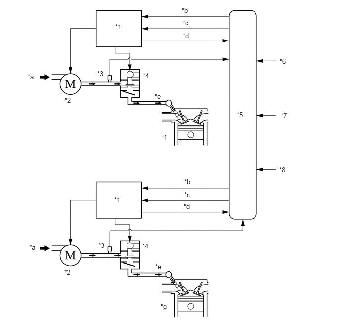
| *1 | Air Injection Control Driver | *2 | Air Pump |
| *3 | Air Pressure Sensor | *4 | Air Switching Valve |
| *5 | ECM | *6 | Engine Coolant Temperature Sensor |
| *7 | Mass Air Flow Meter | *8 | Intake Air Temperature Sensor |
| *a | Air | *b | Pump Actuation Request |
| *c | Valve Actuation Request | *d | Diagnosis Signal |
| *e | To Exhaust Manifold | *f | Bank 2 (Right Bank) |
| *g | Bank 1 (Left Bank) | - | - |
Construction and Operation
Air Pump
Each air pump consists of a DC motor, an impeller and an air filter.
The air pump supplies air into an air injection control valve using its impeller.
The air filter is maintenance-free.
The air pumps for bank 1 and bank 2 have the same basic structure and function.
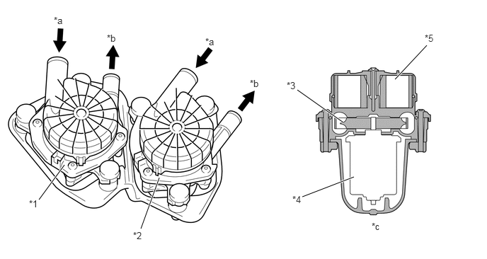
| *1 | Air Pump (Bank 2) | *2 | Air Pump (Bank 1) |
| *3 | Impeller | *4 | DC Motor |
| *5 | Air Filter | - | - |
| *a | Air In | *b | Air Out |
| *c | Cross Section | - | - |
Air Switching Valve
The air switching valve is operated by a DC motor to control air injection and prevent back-flow of exhaust gas. Opening timing of the valve is synchronized with the operation timing of the air pump.
An air pressure sensor is built into the corresponding air switching valve.
The air switching valves for bank 1 and bank 2 have the same basic structure and function.
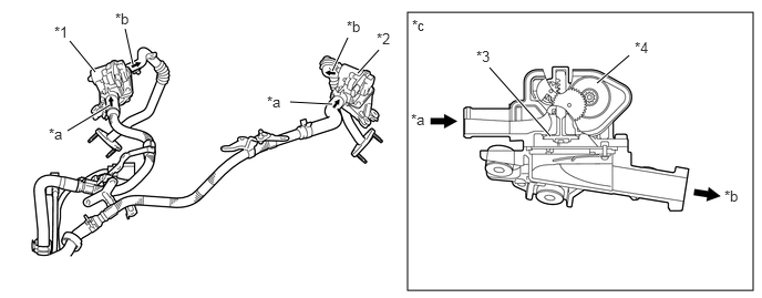
| *1 | Air Switching Valve (Bank 2) | *2 | Air Switching Valve (Bank 1) |
| *3 | Valve | *4 | DC Motor |
| *a | Air In | *b | Air Out |
| *c | Cross Section (for Bank 1) | - | - |
Air Pressure Sensor
The air pressure sensor consists of a semiconductor, which has a silicon chip that changes its electrical resistance when pressure is applied to it. The sensor converts the pressure into an electrical signal, and sends it to the ECM in an amplified form.
The air pressure sensors for bank 1 and bank 2 have the same basic structure and function.
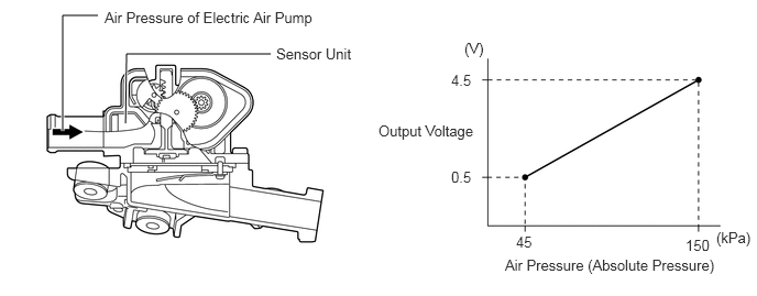
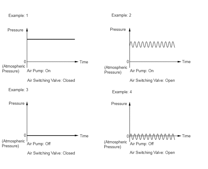
The ECM detects operation of the air injection system based on signals from the air pressure sensor as follows:
When the air pump is on and the air switching valve is closed, the pressure is stable.
When the air pump is on and the air switching valve is open, the pressure drops slightly and becomes unstable because of exhaust pulses.
When the air pump is off and the air switching valve is closed, the pressure remains at atmospheric pressure.
When the air pump is off and the air switching valve is open, the pressure drops below atmospheric pressure and becomes unstable because of exhaust pulses.
Air Injection Control Driver
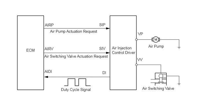
A semiconductor type air injection control driver is used. Activated by the ECM, this driver actuates the air pump and the air switching valve.
The air injection control driver also detects failures in the input and output circuits of the air injection driver and transmits the failure status to the ECM via duty cycle signals.
The air injection control drivers for bank 1 and bank 2 have the same basic structure and function. The following system chart shows the bank 1 (left bank):
| Condition | AIRP | AIRV | Output (Duty Cycle Signal) |
|---|---|---|---|
| Open circuit in line between AIDI and DI terminals. | - | - | 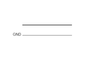
0.469,1.188 0.813,1.604
0.344,0.417
10
false
GND
|
| Failure in line between ECM terminals and air injection control driver. | - | - | 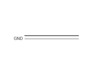
0.458,1.208 0.823,1.583
0.365,0.375
10
false
GND
|
| Output failure at air injection control driver. (Failure in air pump actuation circuit) | - | - | 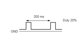
0.458,1.26 0.802,1.688
0.344,0.427
10
false
GND
1.427,0.625 2.031,0.917
0.604,0.292
10
false
200 ms
2.667,0.781 3.302,1.115
0.635,0.333
10
false
Duty 20%
|
| Output failure at air injection control driver. (Failure in air switching valve actuation circuit) | - | - | 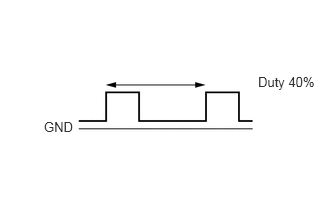
0.458,1.24 0.813,1.625
0.354,0.385
10
false
GND
2.688,0.771 3.333,1.208
0.646,0.438
10
false
Duty 40%
|
| Overheat failure of air injection control driver. | - | - | 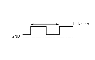
0.417,1.24 0.792,1.583
0.375,0.344
10
false
GND
2.635,0.771 3.292,1.125
0.656,0.354
10
false
Duty 60%
|
| Normal | On | On | 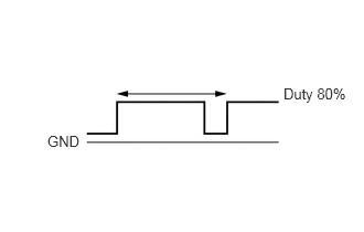
0.448,1.25 0.813,1.635
0.365,0.385
10
false
GND
2.677,0.802 3.313,1.219
0.635,0.417
10
false
Duty 80%
|
| Off | Off |
0.458,1.208 0.823,1.583
0.365,0.375
10
false
GND
|
|
| On | Off | ||
| Off | On |
Starter Control (Cranking Hold Function)
General
Once the ignition switch is turned to the START position, this control continues to operate the starter until the engine starts, without having to hold the ignition switch in the START position. This prevents starting failures.
When the ECM detects a start signal from the ignition switch, this system monitors the engine speed (NE) signal and continues to operate the starter until it determines that the engine has started.
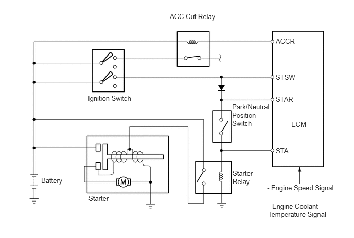
Operation
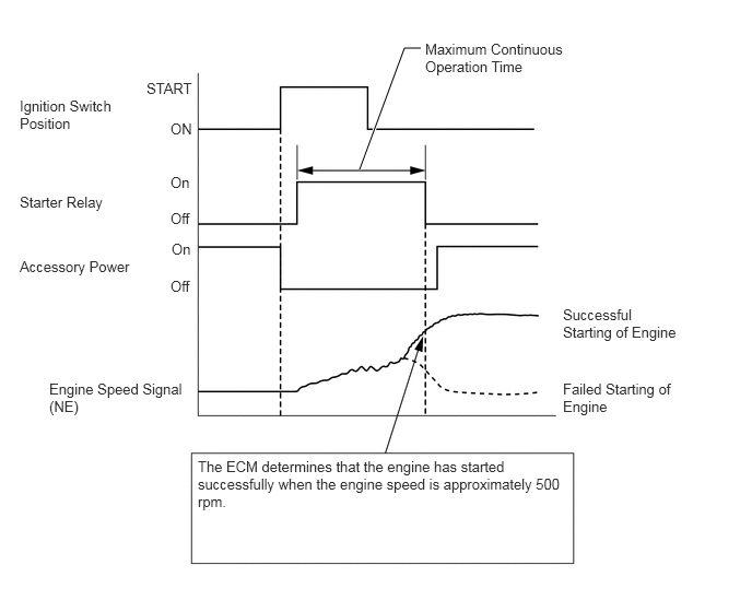
As indicated in the following timing chart, when the ECM detects a start signal from the ignition switch, it energizes the starter relay to operate the starter. If the engine is already running, the ECM will not energize the starter relay.
After the starter operates and the engine speed becomes higher than approximately 500 rpm, the ECM determines that the engine has started and stops the operation of the starter.
If the engine does not start due to a failure, the starter operates as long as its maximum continuous operation time and stops automatically. The maximum continuous operation time varies depending on the engine coolant temperature condition.
This system cuts off the current that powers the accessories while the engine is cranking to prevent the accessory illumination from operating intermittently due to the unstable voltage associated with the cranking of the engine.
This system has the following protections:
In the event that the starter begins to operate, but cannot detect the engine speed signal, the ECM will stop the starter operation immediately. However, if the ignition switch is held in the START position, the starter continues to operate.
Evaporative Emission Control System
General
The evaporative emission control system prevents the fuel vapors created in the fuel tank from being released directly into the atmosphere.
The charcoal canister assembly stores the fuel vapors that have been created in the fuel tank.
The ECM controls the purge VSV in accordance with the driving conditions in order to direct the fuel vapors into the engine, where they are burned.
In this system, the ECM checks for evaporative emission leaks and outputs a Diagnostic Trouble Code (DTC) in the event of a malfunction. An evaporative emission leak check consists of an application of vacuum to the evaporative emission system and monitoring the system for changes in pressure in order to detect a leak.
This system consists of the purge VSV, charcoal canister assembly, canister pump module and ECM.
A refueling vapor recovery function is provided.
A canister pressure sensor has been included with the canister pump module.
A canister filter has been provided on the fresh air line. This canister filter is maintenance-free.
The following are the typical conditions necessary to enable an evaporative emission (EVAP) leak check:
|
*: If engine coolant temperature does not drop below 35°C (95°F), this time is extended to 7 hours. After that, if the temperature is still not less than 35°C (95°F), the time is extended to 9.5 hours. |
|
| Typical Enabling Conditions | ·
5 hours have elapsed after the engine has been turned off*. ·
Altitude: Below 2400 m (8000 feet) ·
Battery Voltage: 10.5 V or more ·
Ignition Switch: Off ·
Engine Coolant Temperature: 4.4°C to 35°C (40°F to 95°F) ·
Intake Air Temperature: 4.4°C to 35°C (40°F to 95°F) |
- HINT:
-
The canister pump module performs a fuel evaporative emission leak check. This check is conducted approximately 5 hours after the engine is turned off. Sound may be heard coming from underneath the luggage compartment for several minutes. This does not indicate a malfunction.
- ·
A pinpoint pressure test procedure is used by pressurizing the fresh air line that runs from the canister pump module to the air filler neck. For details, refer to the Repair Manual.
System Diagram
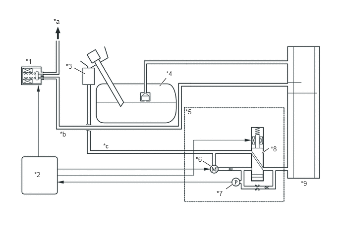
| *1 | Purge VSV | *2 | ECM |
| *3 | Canister Filter | *4 | Fuel Tank Assembly |
| *5 | Canister Pump Module | *6 | Leak Detection Pump |
| *7 | Canister Pressure Sensor | *8 | Vent Valve |
| *9 | Charcoal Canister Assembly | - | - |
| *a | To Intake Manifold | *b | Purge Air Line |
| *c | Fresh Air Line | - | - |
Function of Main Components
| Component | Function | |
|---|---|---|
| ECM | Controls the canister pump module and the purge VSV in accordance with the signals from various sensors, in order to achieve a purge volume that suits the driving conditions. In addition, the ECM monitors the system for any leak and stores a DTC if a malfunction is found. | |
| Charcoal Canister Assembly | Contains activated charcoal to absorb the fuel vapor that is created in the fuel tank assembly. | |
| Fresh Air Line | Fresh air goes into the charcoal canister assembly and the cleaned drain air goes out into the atmosphere. | |
| Canister Pump Module | Vent Valve | Opens and closes the fresh air line in accordance with signals from the ECM. |
| Leak Detection Pump | Applies vacuum to the evaporative emission system in accordance with signals from the ECM. | |
| Canister Pressure Sensor | Detects the pressure in the evaporative emission system and sends the signals to the ECM. | |
| Purge VSV | Opens in accordance with the signals from the ECM when the system is purging, in order to send the fuel vapor that was absorbed by the charcoal canister assembly into the intake manifold. In system monitoring mode, this valve controls the introduction of vacuum into the fuel tank assembly. | |
| Canister Filter | Prevents dust and debris in the fresh air from entering the system. | |
Construction and Operation
Canister Pump Module
The canister pump module consists of a vent valve, reference orifice, canister pressure sensor, leak detection pump, and pump motor.
The vent valve switches the passages in accordance with the signals received from the ECM.
A DC type brushless motor is used for the pump motor.
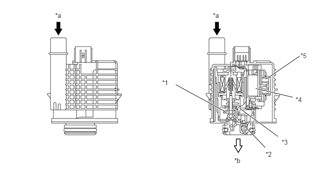
| *1 | Vent Valve | *2 | Reference Orifice |
| *3 | Canister Pressure Sensor | *4 | Pump Motor |
| *5 | Leak Detection Pump | - | - |
| *a | Fresh Air | *b | To Charcoal Canister Assembly |
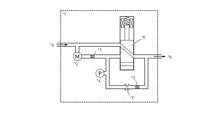
| *1 | Canister Pump Module | *2 | Leak Detection Pump |
| *3 | Filter | *4 | Canister Pressure Sensor |
| *5 | Reference Orifice [0.5 mm (0.020 in.) Diameter] | *6 | Vent Valve (Off) |
| *a | Fresh Air | *b | To Charcoal Canister Assembly |
Fuel Inlet (Fresh Air Inlet)
This evaporative emission control system has its fresh air line inlet located near the fuel inlet. The fresh air from the atmosphere and drain air cleaned by the charcoal canister will go in and out of the system through the passage shown below.
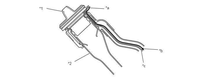
| *1 | Fuel Tank Cap | *2 | Fuel Inlet Pipe |
| *a | Fresh Air | *b | To Charcoal Canister |
| *c | Cleaned Drain Air | - | - |
System Operation
Purge Flow Control
When the engine has reached a predetermined state (closed loop, engine coolant temperature above 80°C (176°F), etc.), stored fuel vapor is purged from the charcoal canister assembly whenever the purge VSV is opened by the ECM.
The ECM will change the duty ratio cycle of the purge VSV, thus controlling purge flow volume. Purge flow volume is determined by intake manifold pressure and the duty ratio cycle of the purge VSV. Atmospheric pressure is allowed into the charcoal canister assembly to ensure that purge flow is constantly maintained whenever purge vacuum is applied to the charcoal canister assembly.
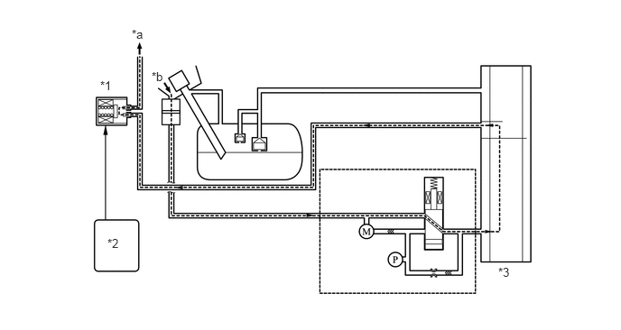
| *1 | Purge VSV (Open) | *2 | ECM |
| *3 | Charcoal Canister Assembly | - | - |
| *a | To Intake Manifold | *b | Atmosphere |
Refueling Vapor Recovery
When the internal pressure of the fuel tank increases during refueling, the fuel vapors enter the charcoal canister assembly. The air that has had the fuel vapors removed from it will be discharged through the fresh air line. The vent valve is used to open and close the fresh air line, and it is always open (even when the engine is stopped) except when the vehicle is in monitoring mode (the valve will be open as long as the vehicle is not in monitoring mode). If the vehicle is refueled in system monitoring mode, the ECM will recognize the refueling by way of the canister pressure sensor, which detects the sudden pressure increase in the fuel tank, and the ECM will open the vent valve.
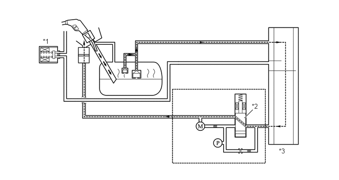
| *1 | Purge VSV (Closed) | *2 | Vent Valve |
| *3 | Charcoal Canister Assembly | - | - |
EVAP Leak Check
General
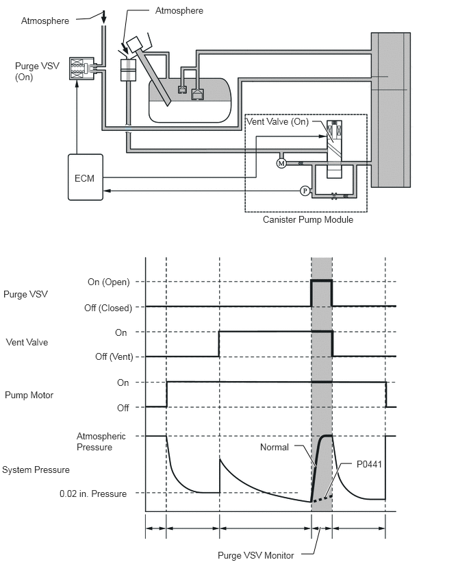
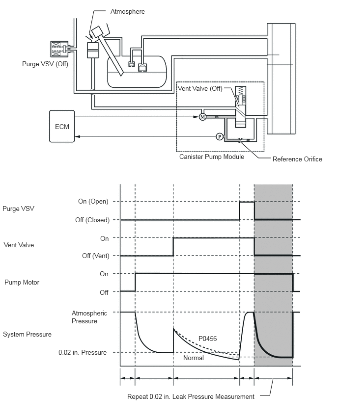
The EVAP leak check operates in accordance with the following timing chart:
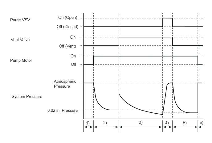
| Order | Operation | Description | Time |
|---|---|---|---|
| 1) | Atmospheric Pressure Measurement | The ECM turns the vent valve off (vent) and measures EVAP system pressure to memorize the atmospheric pressure. | 60 sec. |
| 2) | 0.02 in. Leak Pressure Measurement | The leak detection pump creates negative pressure (vacuum) through a 0.02 in. orifice and the pressure is measured. The ECM determines this as the 0.02 in. leak pressure. | 360 sec. |
| 3) | EVAP Leak Check | The leak detection pump creates negative pressure (vacuum) in the EVAP system and the EVAP system pressure is measured. If the stabilized pressure is larger than the 0.02 in. leak pressure, the ECM determines that the EVAP system has a leak.
If the EVAP pressure does not stabilize within 15 minutes, the ECM cancels EVAP monitor. |
Within 15 min. |
| 4) | Purge VSV Monitor | The ECM opens the purge VSV and measures the EVAP pressure increase. If the increase is large, the ECM interprets this as normal. | 10 sec. |
| 5) | Repeat 0.02 in. Leak Pressure Measurement | The leak detection pump creates negative pressure (vacuum) through the 0.02 in. orifice and the pressure is measured. The ECM determines this as the 0.02 in. leak pressure. | 20 sec. |
| 6) | Final Check | The ECM measures the atmospheric pressure and records the monitor result. | - |
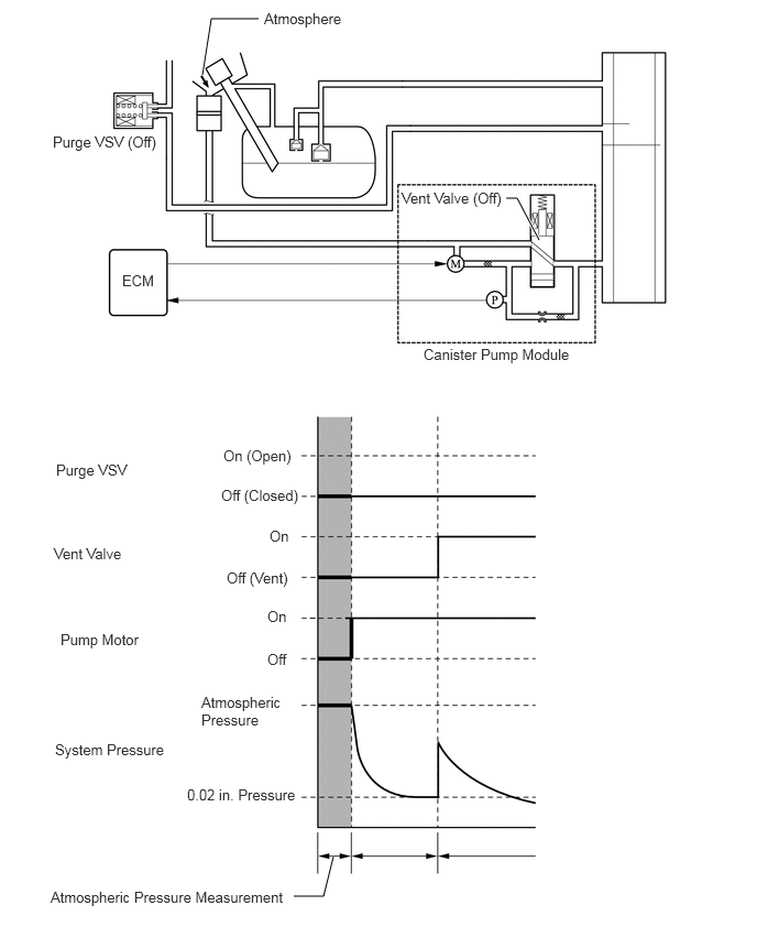
Atmospheric Pressure Measurement
When the ignition switch is turned off, the purge VSV and the vent valve are turned off. As a result, atmospheric pressure is introduced into the charcoal canister assembly.
The ECM measures the atmospheric pressure using the canister pressure sensor.
If the measured atmospheric pressure is out of range, the ECM actuates the leak detection pump in order to monitor the changes in the pressure.
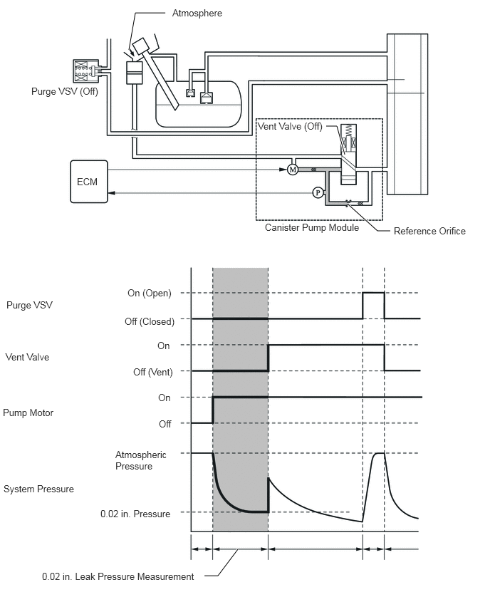
0.02 in. Leak Pressure Measurement
The purpose of this measurement is to confirm leak detection pump operation, and to provide a baseline measurement value that will be used for comparison in subsequent leak test steps.
The vent valve remains off, atmospheric pressure is introduced into the charcoal canister assembly and the ECM actuates the leak detection pump, creating a vacuum in the piping close to the canister pressure sensor.
At this time, the pressure will not decrease below what is referred to as the 0.02 in. pressure due to the atmospheric pressure that enters the piping close to the pump and sensor through the 0.02 in. diameter reference orifice.
The ECM compares this pressure against the standard. If the pressure is within the acceptable range, the ECM stores this pressure as the 0.02 in. leak pressure.
If the pressure is below the standard, the ECM will determine that the reference orifice is clogged and store DTC P043E in its memory.
If the pressure is above the standard, the ECM will determine that a high flow rate pressure is passing through the reference orifice and store DTCs P043F, P2401 and P2402 in its memory.
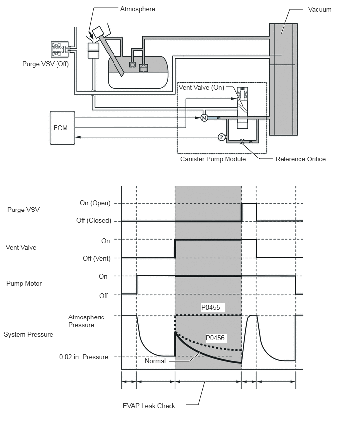
EVAP Leak Check
While actuating the leak detection pump, the ECM turns the vent valve on in order to introduce a vacuum into the charcoal canister assembly.
When the pressure in the system stabilizes, the ECM compares this pressure and the 0.02 in. pressure in order to determine if a leak is present.
If the detected pressure is below the 0.02 in. pressure, the ECM determines that there is no leak.
If the detected pressure is above the 0.02 in. pressure and near atmospheric pressure, the ECM determines that there is a gross leak (large hole) and stores DTC P0455 in its memory.
If the detected pressure is above the 0.02 in. pressure, the ECM determines that there is a small leak (minor leak) and stores DTC P0456 in its memory.
Purge VSV Monitor
After completing an EVAP leak check, the ECM turns the purge VSV on (open) with the leak detection pump actuated, and introduces the atmospheric pressure from the intake manifold to the charcoal canister assembly.
If the pressure change at this time is within the normal range (a pressure change occurs), the ECM determines the condition to be normal.
If the pressure change is out of the normal range (insufficient pressure change occurs), the ECM will stop the purge VSV monitor (purge monitor) and store DTC P0441 in its memory.
Repeat 0.02 in. Leak Pressure Measurement
While the ECM operates the leak detection pump, the purge VSV and vent valve are turned off and a repeat 0.02 in. leak pressure measurement is performed.
The ECM compares the measured pressure with the pressure during the EVAP leak check.
If the pressure during the EVAP leak check is less than the repeat 0.02 in. leak pressure measurement, the ECM determines that there is no leak.
If the pressure during the EVAP leak check is above the repeat 0.02 in. leak pressure measurement, the ECM determines that there is a small leak and stores DTC P0456 in its memory.
Diagnosis
When the ECM detects a malfunction, the ECM makes a diagnosis and memorizes the failed section. Furthermore, the Malfunction Indicator Lamp (MIL) in the combination meter illuminates or blinks to inform the driver.
The ECM will also store the DTC of the malfunctions. The DTC can be accessed by using the Techstream.
For details, refer to the Repair Manual.
- HINT:
-
To clear the DTC that is stored in the ECM, use the Techstream, disconnect the battery terminal or remove the EFI MAIN fuse and ETCS fuse for 1 minute or longer.
Fail-safe
When a malfunction is detected at any of the sensors, there is a possibility of an engine or other malfunction occurring if the ECM continues to control the engine control system in the normal way. To prevent such a problem, the fail-safe function of the ECM either relies on the data stored in memory to allow the engine control system to continue operating, or stops the engine if a hazard is anticipated. For details, refer to the Repair Manual.