CHASSIS TRANSFER GENERAL/CONTROL/DETAILS CONSTRUCTION
General
The construction of the WF1AM transfer is shown below:
An electromagnetic clutch-type synchromesh mechanism is used for smooth engagement from 2WD to 4WD and a silent chain is used to reduce front drive noise.
A planetary gear unit is used in the reduction mechanism.
A transfer shift actuator with a built-in shift motor is used to switch the drive mode (2WD - 4H - 4L).
The L4 position switch on the transfer case detects the high or low status of the transfer gear ratio.
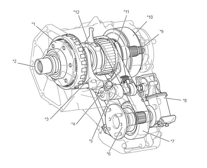
| *1 | Planetary Gear Unit | *2 | Transfer Input Shaft |
| *3 | H-L Shift Fork (No. 1 Transfer Gear Shift Fork Sub-assembly) | *4 | L4 Position Switch (Transfer Indicator Switch) |
| *5 | Transfer Shifter (Control Select Shaft Sub-assembly) | *6 | Transfer Front Output Shaft (Front Output Shaft Companion Flange Sub-assembly) |
| *7 | Silent Chain (Front Transfer Drive Chain) | *8 | Transfer Shift Actuator Assembly |
| *9 | Transfer Rear Output Shaft | *10 | Electromagnetic Clutch-type Synchromesh Mechanism |
| *11 | 2-4 Shift Fork (No. 2 Transfer Gear Shift Fork Sub-assembly) | *12 | Transfer Oil Pump (Transfer Oil Pump Body Sub-assembly) |
Electromagnetic Clutch-type Synchromesh Mechanism
General
The electromagnetic clutch-type synchromesh mechanism contains the electromagnetic clutch solenoid, electromagnetic clutch housing, electromagnetic clutch hub, electromagnetic clutch armature, 2-4 clutch sleeve, 4-wheel drive lock-up hub, lock-up inner hub and front drive sprocket.
The electromagnetic clutch solenoid is attached to the transfer case and produces magnetic force when electricity is supplied from the 4WD control ECU.
The electromagnetic clutch housing is fixed to the rear output shaft via the splined electromagnetic clutch hub and rotates around the electromagnetic clutch solenoid.
The electromagnetic clutch armature is always splined to the 4-wheel drive lock-up hub.
The 4-wheel drive lock-up hub and 2-4 clutch sleeve are splined to the lock-up inner hub that is fixed to the front drive sprocket. When the 2-4 clutch sleeve changes from the 2WD position to the 4H position, the 2-4 clutch sleeve presses against the 4-wheel drive lock-up hub via the spring.
In this electromagnetic clutch-type synchromesh mechanism, the drive torque that is transmitted to the front driveline changes depending on effects from electrical synchronization and the movement of the 4-wheel drive lock-up hub.
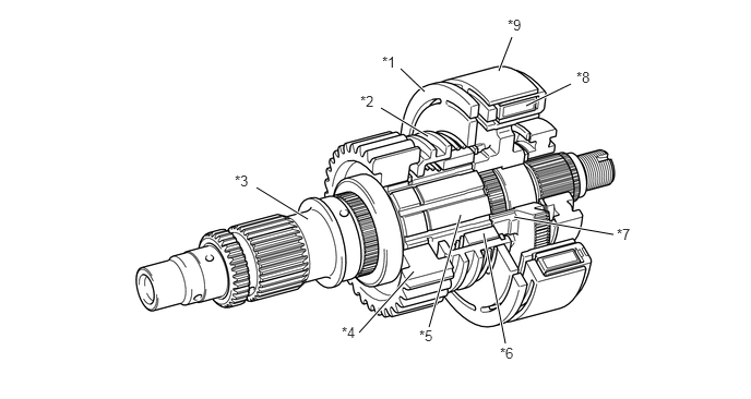
| *1 | Electromagnetic Clutch Armature | *2 | 2-4 Clutch Sleeve |
| *3 | Transfer Rear Output Shaft | *4 | Front Drive Sprocket |
| *5 | Lock-up Inner Hub | *6 | 4-wheel Drive Lock-up Hub |
| *7 | Electromagnetic Clutch Hub | *8 | Electromagnetic Clutch Solenoid (Solenoid Coil Sub-assembly) |
| *9 | Electromagnetic Clutch Housing (Solenoid Cover) | - | - |
Operation
Switching from 2WD to 4WD
When the drive mode is switched from 2WD to 4WD, the 4WD control ECU actuates the electromagnetic clutch solenoid and magnetizes the electromagnetic clutch housing, which in turn pulls and rotates the electromagnetic clutch armature, thereby synchronizing the front driveline and rear driveline. At the same time, the transfer shift actuator operates and the 2-4 clutch sleeve moves rearward.
When the front driveline and rear driveline are synchronized, the 4-wheel drive lock-up hub pressed against the splined 2-4 clutch sleeve via the spring slides and engages with the electromagnetic clutch hub. The lock-up inner hub fixed to the front drive sprocket then connects with the electromagnetic clutch hub.
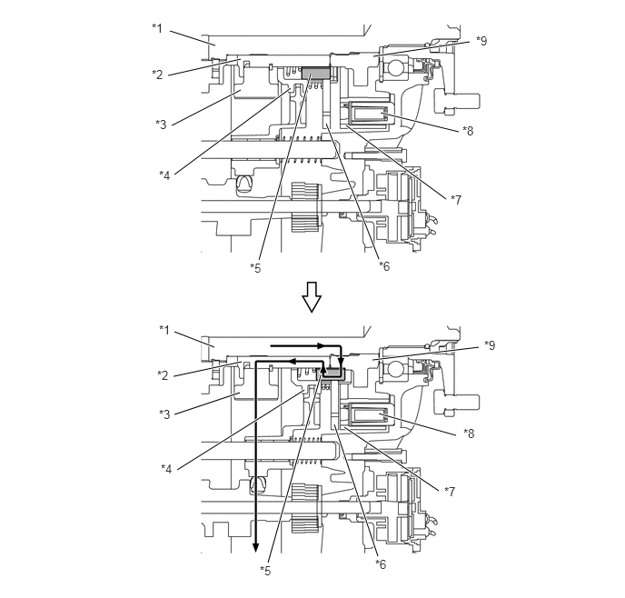
| *1 | Transfer Rear Output Shaft | *2 | Lock-up Inner Hub |
| *3 | Front Drive Sprocket | *4 | 2-4 Clutch Sleeve |
| *5 | 4-wheel Drive Lock-up Hub | *6 | Electromagnetic Clutch Armature |
| *7 | Electromagnetic Clutch Housing | *8 | Electromagnetic Clutch Solenoid |
| *9 | Electromagnetic Clutch Hub | - | - |
Planetary Gear Unit
General
The planetary gear unit consists of a planetary sun gear, 6 planetary pinion gears, 6 pinion gear shafts, a planetary ring gear, a planetary carrier and a reduction hub.
The planetary sun gear is integrated with the transfer input shaft. A spline is located on the rear inner surface of the planetary sun gear.
The 6 planetary pinion gears are fitted to the planetary carrier via the pinion gear shafts. Each pinion gear shaft is fixed to the planetary carrier. A spline is located on the rear inner surface of the planetary carrier.
The planetary ring gear is fixed to the transfer case and its internal teeth mesh with the planetary pinion gears.
The drive torque from the transfer input shaft is transmitted to the transfer rear output shaft via the reduction hub. The reduction hub is installed behind the transfer input shaft that is always splined to the transfer rear output shaft. In this planetary gear unit, the drive torque transmission route changes according to the movement of the reduction hub.
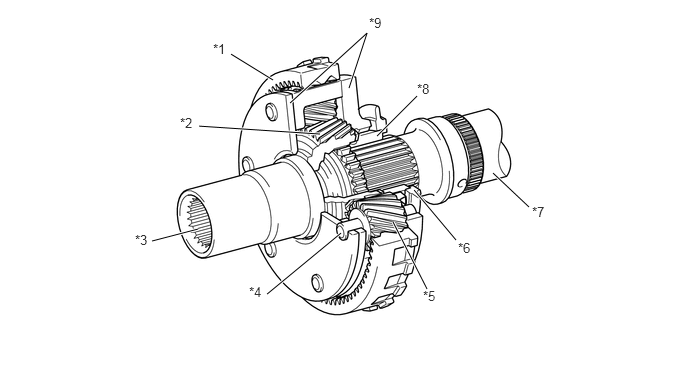
| *1 | Planetary Ring Gear | *2 | Planetary Sun Gear |
| *3 | Transfer Input Shaft | *4 | Pinion Gear Shaft |
| *5 | Planetary Pinion Gear | *6 | H-L Clutch Sleeve (Transfer High and Low Clutch Sleeve) |
| *7 | Transfer Rear Output Shaft | *8 | Reduction Hub |
| *9 | Planetary Carrier | - | - |
Operation
High Position
In the high position, the external spline of the reduction hub is meshed with the internal spline at the rear of the transfer input shaft.
Thus, the rotation of the transfer input shaft is transmitted to the planetary sun gear, reduction hub and transfer rear output shaft.
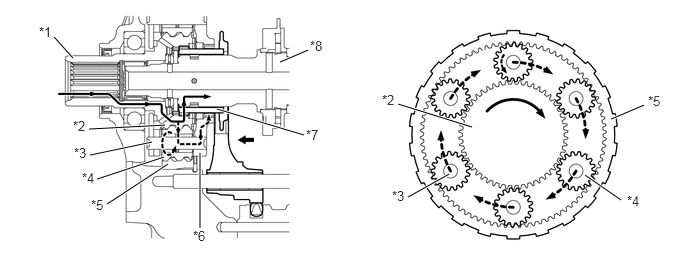
| *1 | Transfer Input Shaft | *2 | Planetary Sun Gear |
| *3 | Pinion Gear Shaft | *4 | Planetary Pinion Gear |
| *5 | Planetary Pinion Gear | *6 | Planetary Carrier |
| *7 | Reduction Hub | *8 | Transfer Rear Output Shaft |
Low Position
In the low position, the external spline of the reduction hub is meshed with the internal spline at the rear of the planetary carrier.
Thus, the rotation of the transfer input shaft is transmitted in a reduced form to the planetary sun gear, planetary pinion gears, pinion gear shafts, planetary carrier, reduction hub and transfer rear output shaft.
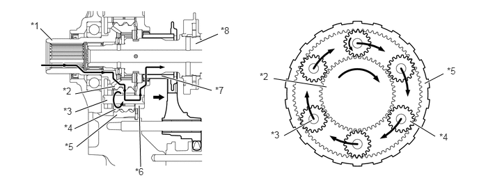
| *1 | Transfer Input Shaft | *2 | Planetary Sun Gear |
| *3 | Pinion Gear Shaft | *4 | Planetary Pinion Gear |
| *5 | Planetary Pinion Gear | *6 | Planetary Carrier |
| *7 | Reduction Hub | *8 | Transfer Rear Output Shaft |
Transfer Shift Actuator
General
The transfer shift actuator contains the transfer shift motor, transfer shifter shaft, spiral springs, transfer shifter and limit switch. It should not be disassembled.
The transfer shift motor rotates the transfer shifter via the spiral springs by rotating the transfer shifter shaft.
Rotation of the transfer shifter causes the 2 shift forks to move separately along a groove in the transfer shifter. This movement of the shift forks allows shifting between 2WD and 4WD and between high and low transfer gear ratios.
The motor encoder is located on the driven gear of the transfer shift motor. The limit switch has 5 contact points (TL1, TL2, TL3, TL4 and GTL) and different combinations of the 5 contact points allow detection of the transfer shift state.
The wait mechanism (spiral spring) is used for transfer shifter operations. If the operating resistance of the transfer shifter is high, the rotation of the transfer shift motor is partially stored in the spiral spring. Later, when the operating resistance is reduced, the spring force causes the transfer shifter to rotate.
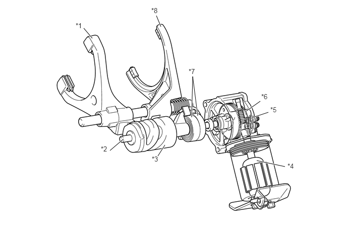
| *1 | H-L Shift Fork (No. 1 Transfer Gear Shift Fork Sub-assembly) | *2 | Transfer Shifter Shaft |
| *3 | Transfer Shifter (Control Select Shaft Sub-assembly) | *4 | Transfer Shift Motor |
| *5 | Limit Switch | *6 | Motor Encoder |
| *7 | Spiral Spring | *8 | 2-4 Shift Fork (No. 2 Transfer Gear Shift Fork Sub-assembly) |
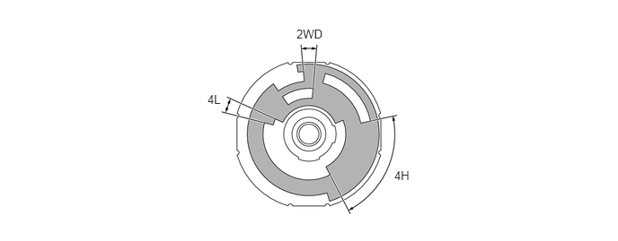
Operation
In the 2WD position, the H-L shift fork and the 2-4 shift fork are located on the front side.
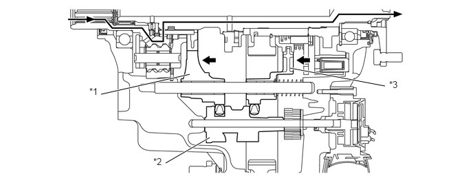
| *1 | H-L Shift Fork (No. 1 Transfer Gear Shift Fork Sub-assembly) | *2 | Transfer Shifter (Control Select Shaft Sub-assembly) |
| *3 | 2-4 Shift Fork (No. 2 Transfer Gear Shift Fork Sub-assembly) | - | - |
In the 4H position, the H-L shift fork is located on the front side and the 2-4 shift fork is located on the rear side.
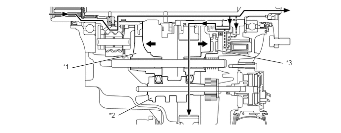
| *1 | H-L Shift Fork (No. 1 Transfer Gear Shift Fork Sub-assembly) | *2 | Transfer Shifter (Control Select Shaft Sub-assembly) |
| *3 | 2-4 Shift Fork (No. 2 Transfer Gear Shift Fork Sub-assembly) | - | - |
In the 4L position, the H-L shift fork and the 2-4 shift fork are located on the rear side.
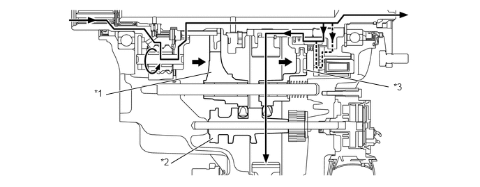
| *1 | H-L Shift Fork (No. 1 Transfer Gear Shift Fork Sub-assembly) | *2 | Transfer Shifter (Control Select Shaft Sub-assembly) |
| *3 | 2-4 Shift Fork (No. 2 Transfer Gear Shift Fork Sub-assembly) | - | - |