CHASSIS BRAKE GENERAL/CONTROL/DETAILS TRAILER BRAKE CONTROL SYSTEM
General
A trailer brake control system is used.
The trailer brake control system uses a trailer brake control ECU to control the trailer brake from the vehicle.
The trailer brake control system performs optimal control by using the appropriate gain (amount of control) and trailer brake type settings.
The state of the system settings is displayed on the multi-information display in the combination meter assembly.
Precaution
When towing a trailer, turn the intuitive parking assist system off.
Before using the trailer brake control system, check that the trailer brake operates normally.
Before using the trailer brake control system, check the compatibility between the trailer brake control system and the trailer brake.
Set the appropriate gain setting to optimally control the trailer brake. When the gain is set to "0", the trailer brake is not controlled. Also, it is necessary to adjust the gain setting when the vehicle load, trailer load, road condition or weather changes.
The trailer brake control amount may decrease in the following condition:
When the Anti-lock Brake System (ABS) function operates and the vehicle decelerates, the trailer brake control amount is reduced as there is a possibility that the trailer may sway and the wheels may lock.
System Diagram
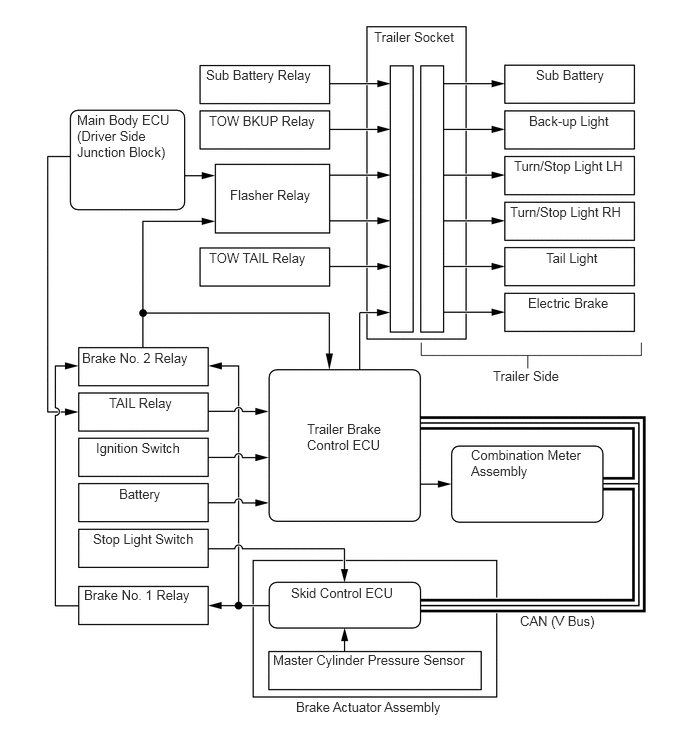
Layout of Main Components
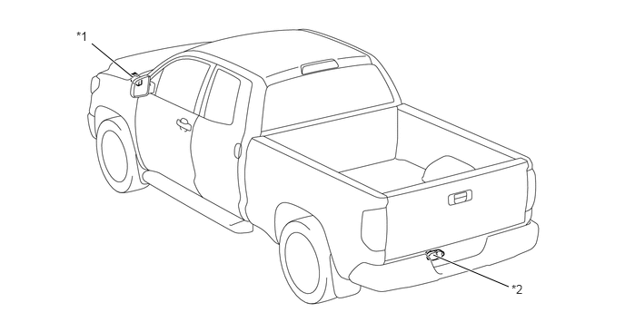
| *1 | Brake Actuator Assembly
·
Skid Control ECU ·
Master Cylinder Pressure Sensor |
*2 | Trailer Socket |
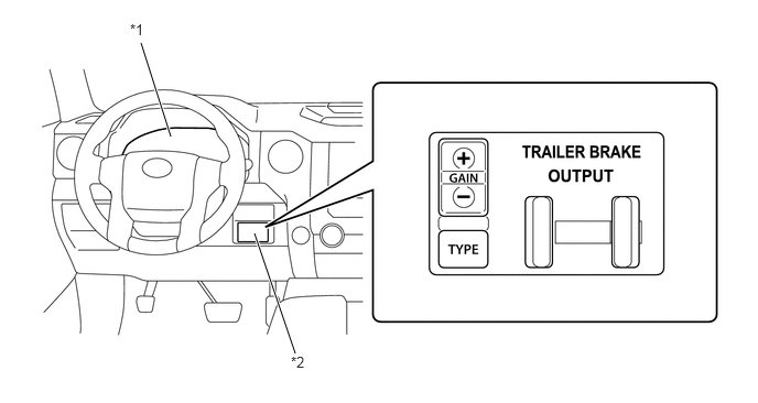
| *1 | Combination Meter Assembly
·
Multi-information Display |
*2 | Trailer Brake Control ECU |
Function of Main Components
| Component | Function | |
|---|---|---|
| Trailer Brake Control ECU | Calculates the output current from the vehicle speed signal, master cylinder pressure sensor signal and state of the system settings (gain and trailer brake type) to control the brake system in the trailer. | |
| Trailer Brake Control ECU | GAIN (+/-) Select Switch | Selects the amount of braking force for the trailer brake. |
| Trailer Brake Type Select Switch | Selects the trailer brake type: electric type or compound type (electric + hydraulic). | |
| Trailer Brake Output Slider | Operates the trailer brake only via manual operation. | |
| Brake Actuator Assembly | Skid Control ECU | Sends the speed sensor and master cylinder pressure sensor signals to the trailer brake control ECU. |
| Master Cylinder Pressure Sensor | Detects the master cylinder pressure. | |
| Combination Meter Assembly | Multi-information Display | ·
Displays a trailer brake control system informations. ·
Displays a warning message when the trailer brake control ECU detects a malfunction in the system. |
System Control
Automatic Control
When the trailer brake control ECU detects that the brake pedal is operated by the driver from the master cylinder pressure sensor signal, the ECU outputs the amount of trailer brake control as an electrical signal according to the gain and trailer brake type settings (maximum output 24 A).
Manual Control
Manual control operates only the trailer brake according to the trailer brake output slider operation from the driver.
When the trailer brake control ECU detects that the trailer brake output slider is operated by the driver, the ECU outputs the amount of trailer brake control as an electrical signal according to the trailer brake output slider position (maximum output 24 A).
When the driver operates the brake pedal (automatic control operates) during manual control operation, the amount of manual control is compared with the amount of automatic control, and the larger amount of trailer brake control is output.
Function
GAIN (+/-) Select Switch
The gain (+/-) select switch sets the amount of trailer brake control output from the trailer brake control ECU.
The amount of trailer brake control can be set from 0 (no trailer braking) to 10 (maximum output) in 0.5 step increments. The gain can be continuously increased or decreased by pressing and holding the appropriate button on the switch.
The set gain is displayed on the multi-information display in the combination meter assembly.
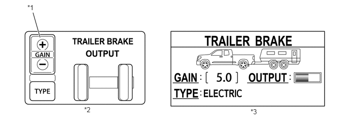
| *1 | Gain (+/-) Select Switch | *2 | Trailer Brake Control ECU |
| *3 | Multi-information Display | - | - |
- HINT:
- ·
The gain must be appropriately set for the trailer brake control system to perform optimal control.
·Adjust the gain setting every time the vehicle load, trailer load, road condition or weather changes.
·When towing a trailer at speeds of 20 km/h to 25 km/h (12.4 mph to 15.5 mph), set the trailer brake output slider to the maximum so that the gain setting operates the trailer brake with the maximum output. At this time, set the gain to 1 step below the level at which the trailer wheels lock.
Trailer Brake Type Select Switch
The trailer brake type select switch selects the trailer brake type.
2 types of trailer brakes are available: electric type or compound type (electric + hydraulic).
The set trailer brake type is displayed on the multi-information display in the combination meter assembly.
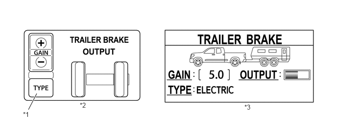
| *1 | Trailer Brake Type Select Switch | *2 | Trailer Brake Control ECU |
| *3 | Multi-information Display | - | - |
Diagnosis
If the trailer brake control ECU detects a malfunction in the trailer brake control system, warning message displays on the multi-information display. At the same time, a Diagnostic Trouble Code (DTC) is stored in the trailer brake control ECU. For details of DTC, refer to the Repair Manual.