BODY ELECTRICAL INTUITIVE PARKING ASSIST SYSTEM GENERAL/CONTROL/DETAILS CONSTRUCTION AND OPERATION
ULTRASONIC SENSOR
Each ultrasonic sensor transmits ultrasonic waves, receives the reflected waves from an obstacle, and transmits a signal to the clearance warning ECU regarding the distance to the obstacle.
The frequency used by the ultrasonic sensors varies as shown below, depending on the installation position of the ultrasonic sensors.
| Ultrasonic Sensor | Frequency |
|---|---|
| Front and Rear Corner | 45.7 kHz |
| Back | 58.8 kHz |
BUZZER
Depending on the detection distance and the detection area, the sound pattern of the buzzer will vary.
| Detection Area | Detection Distance | mm (in.) | Buzzer ON/OFF Time (msec.) | ||
|---|---|---|---|---|---|
| ON | OFF | ||||
| Front Corner | Long | 600 +/- 60 to 400 +/- 40
(23.6 +/- 2.4 to 15.7 +/- 1.6) |
150 +/- 15 | 150 +/- 15 | |
| Middle | 400 +/- 40 to 250 +/- 30
(15.7 +/- 1.6 to 9.8 +/- 1.1) |
75 +/- 7.5 | 75 +/- 7.5 | ||
| Short | 250 +/- 30 or less
(9.8 +/- 1.1 or less) |
Continuous Sound | 0 | ||
| Rear Corner | Long | 850 +/- 90 to 520 +/- 50
(33.5 +/- 3.4 to 20.5 +/- 2.1) |
150 +/- 15 | 150 +/- 15 | |
| Middle | 520 +/- 50 to 400 +/- 40
(20.5 +/- 2.1 to 15.7 +/- 1.6) |
75 +/- 7.5 | 75 +/- 7.5 | ||
| Short | 400 +/- 40 or less
(15.7 +/- 1.6 or less) |
Continuous Sound | 0 | ||
| Back | Long | 1800 +/- 180 to 1150 +/- 120
(70.9 +/- 7.1 to 45.7 +/- 4.6) |
150 +/- 15 | 150 +/- 15 | |
| Middle | 1150 +/- 120 to 850 +/- 90
(45.7 +/- 4.6 to 33.5 +/- 3.4) |
75 +/- 7.5 | 75 +/- 7.5 | ||
| Short | 850 +/- 90 or less
(33.5 +/- 3.4 or less) |
Continuous Sound | 0 | ||
MULTI-INFORMATION DISPLAY
The items displayed by the multi-information display are the location of the obstacle and the approximate distance between the vehicle and the obstacle, warning messages relating to sensor malfunction, sensor freezing, or presence of dirt on the sensor. When any warning messages are displayed the buzzer sounds.
The number of lines indicates the distance to an obstacle. As the distance to an obstacle decreases, the number of lines also decreases to indicate the change in distance. Yellow lines indicate a long or medium-range distance, and red lines indicate a close-range distance.
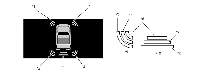
| *1 | Front Corner LH | *2 | Rear Corner LH |
| *3 | Rear Center | *4 | Rear Corner RH |
| *5 | Front Corner RH | *6 | Long-range Detection |
| *7 | Medium-range Detection | *8 | Close-range Detection |
| *9 | Front and Rear Corner | *10 | Rear Center |
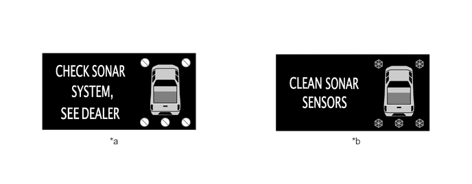
| *a | Ultrasonic Sensor Malfunction Warning | *b | Ultrasonic Sensor Freeze/Contamination Warning |
CLEARANCE SONAR ECU
The Clearance Sonar ECU effects overall control of the system, including the switching of the transmitting and reception of the ultrasonic sensor signals, processing the received wave signals, determining the presence of obstacles, actuating the buzzer, and determining the presence of a malfunction in the sensors.
The sound volume of the buzzer in the accessory meter can be adjusted at the Clearance Sonar ECU.
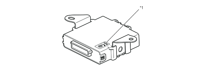
| *1 | Buzzer Sound Volume Adjustment Screw | - | - |