Home › Engine / Hybrid System › 3UR-FBE ENGINE CONTROL › EFI RELAY
RM27M0U _51 Engine / Hybrid System _049095 3UR-FBE ENGINE CONTROL _0233941 EFI RELAY G

3UR-FBE ENGINE CONTROL  EFI RELAY  ON-VEHICLE INSPECTION  


PROCEDURE

Hide 1.REMOVE INTEGRATION RELAY (UNIT E)

a.

Remove the engine room relay block cover.
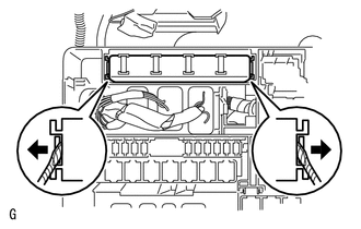

b.
A155875

Using a screwdriver, detach the 2 claws and remove the integration relay from the engine room relay block.

HINT:

Tape the screwdriver tip before use.


c.

Disconnect the 3 connectors.


Hide 2.INSPECT INTEGRATION RELAY (EFI RELAY)

NOTICE:
·

Some relays are built into the integration relay (unit E). The integration relay cannot be disassembled. If there is a malfunction in the circuit of the integration relay, replace the integration relay.

·

The internal circuit of the integration relay is as shown in the illustration below. Inspect the integration relay using the following procedures.
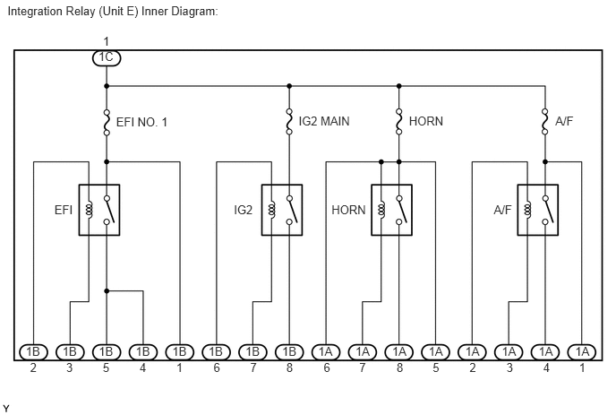


A186178E01
0.087,0.037 2.762,0.246 2.675,0.209 10 Integration Relay (Unit E) Inner Diagram: 1.145,0.577 1.367,0.730 0.222,0.152 10 1C 1.198,0.398 1.319,0.561 0.121,0.163 10 1 0.299,4.004 0.503,4.176 0.204,0.172 10 1B 0.726,4.004 0.930,4.176 0.204,0.172 10 1B 1.149,4.004 1.353,4.176 0.204,0.172 10 1B 1.578,4.004 1.783,4.176 0.204,0.172 10 1B 2.004,4.004 2.208,4.176 0.204,0.172 10 1B 2.425,4.004 2.630,4.176 0.204,0.172 10 1B 2.855,4.004 3.059,4.176 0.204,0.172 10 1B 3.282,4.004 3.486,4.176 0.204,0.172 10 1B 3.702,4.004 3.907,4.176 0.204,0.172 10 1A 4.135,4.004 4.339,4.176 0.204,0.172 10 1A 4.562,4.004 4.767,4.176 0.204,0.172 10 1A 4.986,4.004 5.190,4.176 0.204,0.172 10 1A 5.412,4.004 5.617,4.176 0.204,0.172 10 1A 5.838,4.004 6.042,4.176 0.204,0.172 10 1A 6.266,4.004 6.470,4.176 0.204,0.172 10 1A 6.691,4.004 6.895,4.176 0.204,0.172 10 1A 0.35,4.189 0.458,4.352 0.107,0.163 10 2 0.77,4.189 0.895,4.332 0.125,0.143 10 3 1.196,4.189 1.310,4.343 0.114,0.154 10 5 1.623,4.189 1.741,4.343 0.118,0.154 10 4 2.05,4.189 2.157,4.343 0.107,0.154 10 1 2.484,4.189 2.606,4.336 0.122,0.147 10 6 2.911,4.189 3.025,4.345 0.114,0.156 10 7 3.331,4.189 3.451,4.345 0.119,0.156 10 8 3.765,4.189 3.888,4.336 0.122,0.147 10 6 4.18,4.189 4.294,4.345 0.114,0.156 10 7 4.614,4.189 4.734,4.345 0.119,0.156 10 8 5.034,4.189 5.148,4.343 0.114,0.154 10 5 5.462,4.189 5.569,4.352 0.107,0.163 10 2 5.892,4.189 6.016,4.332 0.125,0.143 10 3 6.319,4.189 6.437,4.343 0.118,0.154 10 4 6.736,4.189 6.843,4.343 0.107,0.154 10 1 0.633,2.355 0.905,2.534 0.272,0.179 10 EFI 3.857,2.355 4.315,2.561 0.458,0.206 10 HORN 5.745,2.355 6.034,2.515 0.290,0.160 10 A/F 1.351,1.33 2.065,1.518 0.714,0.188 10 EFI NO. 1 3.474,1.318 4.144,1.479 0.671,0.162 10 IG2 MAIN 4.758,1.321 5.223,1.493 0.465,0.172 10 HORN 6.461,1.322 6.722,1.492 0.260,0.170 10 A/F 2.721,2.355 3.015,2.513 0.294,0.158 10 IG2

a.

Measure the resistance of the EFI No. 1 fuse.

i.

Measure the resistance according to the value(s) in the table below.

Standard Resistance:
Tester Connection Condition Specified Condition
EFI NO. 1 fuse Always Below 1 Ω


If the result is not as specified, replace the EFI No. 1 fuse.


b.
U151388E02
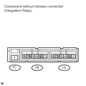
0.49,2.604 0.708,2.792 0.219,0.188 10 false 1C 1.396,2.615 1.615,2.823 0.219,0.208 10 false 1B 2.469,2.625 2.677,2.813 0.208,0.188 10 false 1A 0.167,0.167 2.646,0.552 2.479,0.385 10 false Component without harness connected: (Integration Relay)

Measure the resistance of the EFI relay circuit.

i.

Measure the resistance according to the value(s) in the table below.

Standard Resistance:
Tester Connection Condition Specified Condition
1C-1 - 1B-4
1C-1 - 1B-5
When battery voltage is not applied to terminals 1B-2 and 1B-3 10 kΩ or higher
When battery voltage is applied to terminals 1B-2 and 1B-3 Below 1 Ω


If the result is not as specified, replace the integration relay.


Hide 3.INSTALL INTEGRATION RELAY (UNIT E)

a.

Connect the 3 connectors.


b.

Install the integration relay to the engine room relay block.


c.

Install the engine room relay block cover.