RM27M0U
_51
Engine / Hybrid System
_049101
1UR-FE EMISSION CONTROL
_0233990
AIR SWITCHING VALVE(for Bank 1)
A
1UR-FE EMISSION CONTROL AIR SWITCHING VALVE(for Bank 1) INSTALLATION
PROCEDURE

 25710
1.INSTALL AIR SWITCHING VALVE ASSEMBLY
a.
1.406,0.146 2.208,0.146
2.208,0.146 2.49,0.49
false
1.333,0.594 1.542,0.594
1.542,0.594 1.729,0.927
false
2.323,1.083 2.323,1.396
false
1.104,0.521 1.302,0.708
0.198,0.188
10
false
*1
1.188,0.073 1.365,0.271
0.177,0.198
10
false
*2
2.25,1.417 2.438,1.604
0.188,0.188
10
false
*a
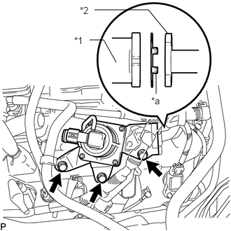
Install a new gasket and the air switching valve assembly with the 3 bolts.
- Torque:
- 24 N*m (245 kgf*cm, 18 ft.*lbf)
| *1 | Air Switching Valve Assembly |
| *2 | No. 4 Air Tube |
| *a | Claw |
- NOTICE:
-
Make sure the gasket's claws are not caught between the air switching valve assembly and No. 4 air tube.
b.
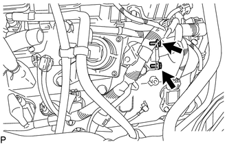
Install the 2 bolts.
- Torque:
- 10 N*m (102 kgf*cm, 7 ft.*lbf)
c.
Connect the wire harness clamp bracket to the cylinder head cover sub-assembly LH with the bolt.
- Torque:
- 8.0 N*m (82 kgf*cm, 71 in.*lbf)
2.CONNECT NO. 2 AIR HOSE
a.
2.26,0.125 2.417,0.125
2.417,0.125 2.802,0.99
true
2.094,1.948 2.208,1.948
2.208,1.948 2.594,1.125
true
1.896,1.854 2.094,2.052
0.198,0.198
10
true
*a
2.052,0.042 2.24,0.24
0.188,0.198
10
true
*b
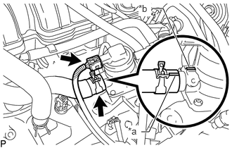
Align the paint mark with the projection and connect the No. 2 air hose, and slide the clamp to secure the hose.
| *a | Paint Mark |
| *b | Projection |
- HINT:
-
Make sure the direction of the hose clamp is as shown in the illustration.
b.
Connect the air switching valve assembly connector.