AB60F AUTOMATIC TRANSMISSION / TRANSAXLE SHIFT LEVER ASSEMBLY(for Floor Shift Type) ADJUSTMENT
PROCEDURE

 1.INSPECT SHIFT LEVER POSITION
When moving the shift lever from N to other positions, check that the lever can be shifted smoothly and accurately to each position and that the position indicator comes on in accordance with the shift lever position.
If the indicator and shift lever position do not match, carry out the following adjustment procedures.
2.ADJUST SHIFT LEVER POSITION
Move the shift lever to N.
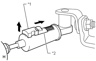
Fold back the transmission control cable adjust case cover. Then while sliding the slider toward the cable end side, press the lock piece from the back side to release the lock.
| *1 | Lock Piece |
| *1 | Slider |
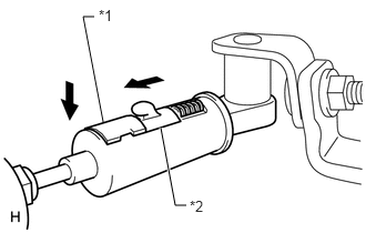
Check that the adjust case's spring is applying enough tension to the shift control cable. Then press the lock piece to set the lock.
| *1 | Lock Piece |
| *1 | Slider |
- NOTICE:
- ·
Use your hand to push the lock piece. Do not use any tools.
·Securely push the lock piece so that the protrusion of the slider is above the lock piece.
Return the cover of the adjust case to its original position.
Inspect the operation after the adjustment.