RM27M0U
_58
Vehicle Interior
_049133
LIGHTING
_0234246
STOP LIGHT SWITCH
A
LIGHTING STOP LIGHT SWITCH INSTALLATION
PROCEDURE

 84345
1.INSTALL STOP LIGHT SWITCH MOUNTING ADJUSTER
a.
Attach the 2 claws to install a new stop light switch mounting adjuster.
84340
2.INSTALL STOP LIGHT SWITCH ASSEMBLY
1.313,1.854 1.167,2.719
false
2.146,1.219 2.26,0.448
false
0.854,1.552 0.521,1.438
false
0.344,1.323 0.531,1.5
0.188,0.177
10
false
*1
1.052,2.74 1.24,2.917
0.188,0.177
10
false
*2
2.177,0.281 2.365,0.458
0.188,0.177
10
false
*3
a.
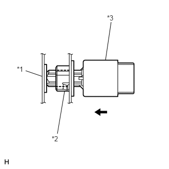
Install the stop light switch assembly to the stop light switch mounting adjuster until the switch body slightly touches the brake pedal.
- NOTICE:
-
Do not depress the brake pedal.
| *1 | Brake Pedal |
| *2 | Stop Light Switch Mounting Adjuster |
| *3 | Stop Light Switch Assembly |
b.
0.179,0.791 0.371,0.970
0.192,0.179
10
*1
1.783,1.648 1.975,1.827
0.192,0.179
10
*2
0.757,1.769 0.949,1.948
0.192,0.179
10
*a
0.689,0.97 0.375,0.886
false
1.873,1.346 1.873,1.626
false
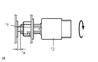
Rotate the stop light switch assembly clockwise so that the clearance is between 1.5 and 2.5 mm (0.0590 and 0.0984 in.) as shown in the illustration.
- NOTICE:
-
Do not depress the brake pedal.
| *1 | Shaft |
| *2 | Stop Light Switch Assembly |
| *a | 1.5 to 2.5 mm |
c.
Check the stop light switch assembly clearance.
- Stop light switch assembly clearance:
1.5 to 2.5 mm (0.0590 to 0.0984 in.)
d.
Connect the connector to the stop light switch assembly.
e.
Install the stop light switch cover.