LIGHTING LIGHTING SYSTEM Illumination Circuit
WIRING DIAGRAM
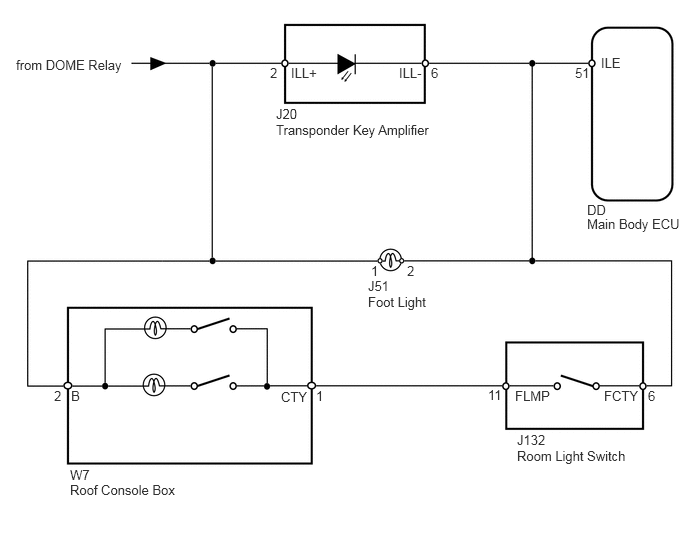
CAUTION / NOTICE / HINT
- HINT:
-
Inspect the bulbs for circuits related to this system before performing the following inspection procedure.
PROCEDURE
Operate the Techstream according to the steps on the display and select "Active Test".
| Tester Display | Test Part | Control Range | Diagnostic Note |
|---|---|---|---|
| Relay for Interior Light Auto Cut Function | DOME relay | ON or OFF | - |
| Result | Proceed to |
|---|---|
| OK | A |
| NG (Only transponder key light does not turn on) | B |
| NG (Only foot light does not turn on) | C |
| NG (Only roof console light does not turn on) | D |
A
B
C
D
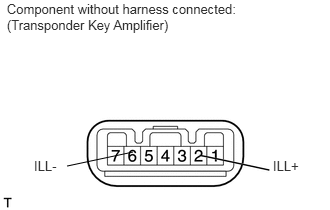
Remove the transponder key amplifier (see page Vehicle Interior>ENGINE IMMOBILISER>TRANSPONDER KEY AMPLIFIER>REMOVAL).
Connect the battery's positive (+) lead to terminal 2 (ILL+) and the negative (-) lead to terminal 6 (ILL-), and then check that the light turns on.
- OK:
Transponder key light turns on.
OK
NG
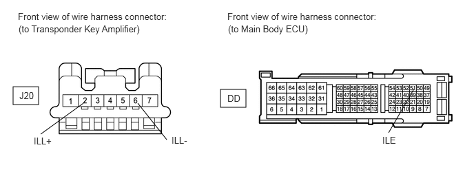
Disconnect the J20 amplifier connector.
Disconnect the DD ECU connector.
Measure the voltage according to the value(s) in the table below.
- Standard voltage:
Tester Connection Condition Specified Condition J20-2 (ILL+) - Body ground Battery saving control (interior light auto cut function) not operating 11 to 14 V
Measure the resistance according to the value(s) in the table below.
- Standard resistance:
Tester Connection Condition Specified Condition J20-6 (ILL-) - DD-51 (ILE) Always Below 1 Ω J20-6 (ILL-) - Body ground Always 10 kΩ or higher
OK
NG
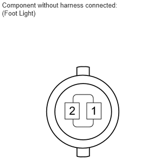
Remove the foot light (see page Vehicle Interior>LIGHTING>FOOTWELL LIGHT>REMOVAL).
Connect the battery's positive (+) lead to terminal 2 and the negative (-) lead to terminal 1, and then check that the light turns on.
- OK:
Foot light turns on.
OK
NG
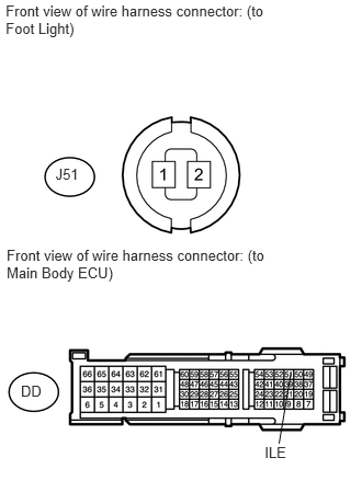
Disconnect the J51 light connector.
Disconnect the DD ECU connector.
Measure the voltage according to the value(s) in the table below.
- Standard voltage:
Tester Connection Condition Specified Condition J51-1 - Body ground Battery saving control (interior light auto cut function) not operating 11 to 14 V
Measure the resistance according to the value(s) in the table below.
- Standard resistance:
Tester Connection Condition Specified Condition J51-2 - DD-51 (ILE) Always Below 1 Ω J51-2 - Body ground Always 10 kΩ or higher
OK
NG
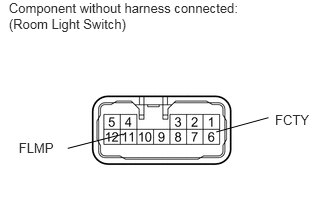
Remove the room light switch (see page Vehicle Interior>LIGHTING>ROOM LIGHT ASSEMBLY>REMOVAL).
Measure the resistance according to the value(s) in the table below.
- Standard resistance:
Tester Connection Switch Condition Specified Condition 6 (FCTY) - 11 (FLMP) Room light switch DOOR Below 1 Ω
OK
NG
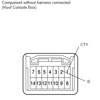
Remove the roof console box (see page Vehicle Interior>LIGHTING>PERSONAL LIGHT ASSEMBLY>REMOVAL).
Roof console box switch is DOOR.
Connect the battery's positive (+) lead to terminal 2 (B) and the negative (-) lead to terminal 1 (CTY), and then check that the light turns on.
- OK:
Map light turns on.
OK
NG
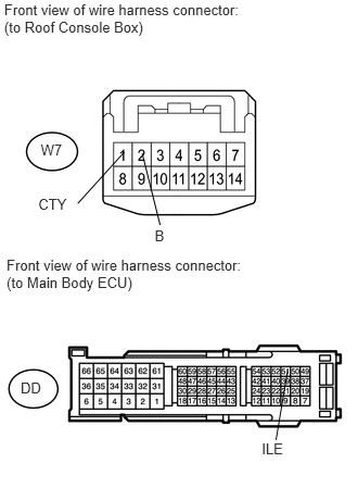
Disconnect the W7 box connector.
Disconnect the DD ECU connector.
Measure the voltage according to the value(s) in the table below.
- Standard voltage:
Tester Connection Condition Specified Condition W7-2 (B) - Body ground Battery saving control (interior light auto cut function) not operating 11 to 14 V
Measure the resistance according to the value(s) in the table below.
- Standard resistance:
Tester Connection Switch Condition Specified Condition W7-1 (CTY) - DD-51 (ILE) Room light switch DOOR Below 1 Ω W7-1 (CTY) - Body ground Room light switch DOOR 10 kΩ or higher
OK
NG