Home › Vehicle Interior › LIGHTING › LIGHTING SYSTEM
RM27M0U _58 Vehicle Interior _049133 LIGHTING _0234252 LIGHTING SYSTEM J

LIGHTING  LIGHTING SYSTEM  Headlight Signal Circuit  


DESCRIPTION

The main body ECU receives a headlight Lo switch information signal from the light control switch, and illuminates the headlight low beam.

WIRING DIAGRAM
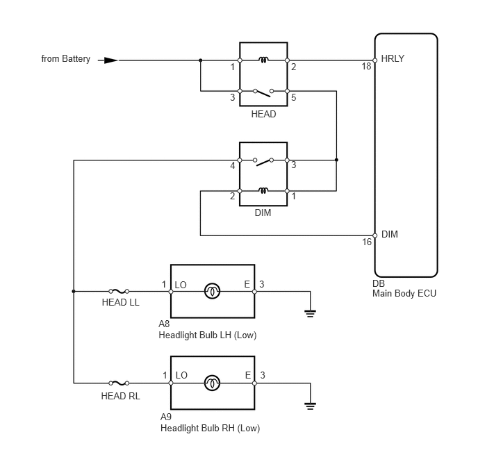
E282214E01
2.406,6.172 2.678,6.340 0.272,0.167 10 A9 2.42,4.174 2.526,4.341 0.106,0.167 10 1 3.887,4.174 3.993,4.341 0.106,0.167 10 3 2.378,4.934 3.937,5.101 1.559,0.167 10 Headlight Bulb LH (Low) 2.378,4.77 3.224,4.938 0.846,0.167 10 A8 2.406,6.33 4.182,6.497 1.776,0.167 10 Headlight Bulb RH (Low) 1.527,4.45 2.141,4.615 0.614,0.165 10 HEAD LL 1.515,5.858 2.139,6.023 0.623,0.165 10 HEAD RL 3.766,1.623 4.191,1.783 0.424,0.161 10 HEAD 4.366,0.922 4.508,1.082 0.142,0.161 10 2 3.449,1.38 3.591,1.540 0.142,0.161 10 3 4.366,1.38 4.508,1.540 0.142,0.161 10 5 3.449,0.913 3.591,1.073 0.142,0.161 10 1 0.619,0.791 1.437,0.970 0.818,0.179 10 from Battery 5.416,0.908 5.589,1.064 0.173,0.156 10 18 5.714,0.796 6.121,0.946 0.407,0.150 10 HRLY 5.583,4.308 6.609,4.450 1.026,0.142 10 Main Body ECU 5.583,4.172 6.609,4.314 1.026,0.142 10 DB 3.818,3.103 4.242,3.263 0.424,0.161 10 DIM 5.424,3.547 5.640,3.702 0.216,0.156 10 16 5.719,3.43 6.126,3.580 0.407,0.150 10 DIM 4.366,2.384 4.508,2.544 0.142,0.161 10 3 3.449,2.393 3.591,2.554 0.142,0.161 10 4 3.449,2.851 3.591,3.011 0.142,0.161 10 2 4.366,2.851 4.508,3.011 0.142,0.161 10 1 2.618,4.183 2.876,4.376 0.258,0.193 10 LO 3.66,4.181 3.917,4.374 0.258,0.193 10 E 2.434,5.537 2.540,5.705 0.106,0.167 10 1 3.901,5.537 4.007,5.705 0.106,0.167 10 3 2.632,5.546 2.890,5.739 0.258,0.193 10 LO 3.674,5.545 3.931,5.738 0.258,0.193 10 E

CAUTION / NOTICE / HINT

HINT:

Inspect the bulbs for circuits related to this system before performing the following inspection procedure.


PROCEDURE

1.PERFORM ACTIVE TEST USING TECHSTREAM (HEADLIGHT)
a.

Operate the Techstream according to the steps on the display and select "Active Test".

Main Body ECU
Tester Display Test Part Control Range Diagnostic Note
Headlight Headlight ON or OFF -

OK:

Headlight low beam turns on / turns off.


OK

PROCEED TO NEXT CIRCUIT INSPECTION SHOWN IN PROBLEM SYMPTOMS TABLE

NG

2.INSPECT FUSE (HEAD LL, HEAD RL)
a.

Remove the HEAD LL and HEAD RL fuses from the engine room junction block.


b.

Measure the resistance according to the value(s) in the table below.

Standard resistance:
Tester Connection Condition Specified Condition
HEAD LL fuse Always Below 1 Ω
HEAD RL fuse


OK

3.CHECK HARNESS AND CONNECTOR (HEADLIGHT LOW BULB - BATTERY)

NG

REPLACE FUSE

3.CHECK HARNESS AND CONNECTOR (HEADLIGHT LOW BULB - BATTERY)
U152892E02
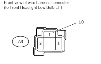
1.792,1.115 2.604,0.781 true 0.135,0 2.51,0.365 2.375,0.365 10 false Front view of wire harness connector: (to Front Headlight Low Bulb LH) 0.615,1.333 0.844,1.5 0.229,0.167 10 false A8 2.677,0.667 2.906,0.833 0.229,0.167 10 false LO

a.

for LH:

i.

Disconnect the A8 headlight connector.


ii.

Measure the voltage according to the value(s) in the table below.

Standard voltage:
Tester Connection Switch Condition Specified Condition
A8-1 (LO) - Body ground Light control switch HEAD, dimmer switch Low 11 to 14 V
Light control switch HEAD, dimmer switch except Low Below 1 V


U152893E02
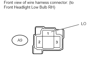
1.792,1.125 2.771,0.865 true 0.135,0 2.573,0.688 2.438,0.688 10 false Front view of wire harness connector: (to Front Headlight Low Bulb RH) 0.615,1.333 0.844,1.5 0.229,0.167 10 false A9 2.844,0.75 3.063,0.927 0.219,0.177 10 false LO

b.

for RH:

i.

Disconnect the A9 headlight connector.


ii.

Measure the voltage according to the value(s) in the table below.

Standard voltage:
Tester Connection Switch Condition Specified Condition
A9-1 (LO) - Body ground Light control switch HEAD, dimmer switch Low 11 to 14 V
Light control switch HEAD, dimmer switch except Low Below 1 V


OK

REPAIR OR REPLACE HARNESS OR CONNECTOR (HEADLIGHT LOW BULB - BODY GROUND)

NG

4.INSPECT HEADLIGHT RELAY (HEAD)
A111813E26
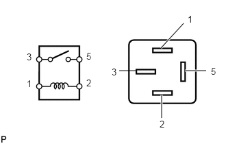
2.448,0.729 2.792,0.354 true 2.813,1.073 3.135,1.073 true 2.063,1.073 1.813,1.073 false 2.458,1.438 2.458,1.792 true 2.854,0.208 3.01,0.375 0.156,0.167 10 false 1 0.406,1.188 0.563,1.354 0.156,0.167 10 false 1 1.698,1.01 1.854,1.177 0.156,0.167 10 false 3 0.406,0.781 0.563,0.948 0.156,0.167 10 false 3 2.427,1.802 2.583,1.969 0.156,0.167 10 false 2 1.313,1.177 1.469,1.344 0.156,0.167 10 false 2 3.208,1 3.365,1.167 0.156,0.167 10 false 5 1.313,0.771 1.469,0.938 0.156,0.167 10 false 5

a.

Remove the headlight relay from the engine room relay block.


b.

Measure the resistance according to the value(s) in the table below.

Standard resistance:
Tester Connection Condition Specified Condition
3 - 5 When battery voltage is not applied to terminals 1 and 2 10 kΩ or higher
When battery voltage is applied to terminals 1 and 2 Below 1 Ω


OK

5.CHECK HARNESS AND CONNECTOR (HEADLIGHT RELAY [HEAD] - BATTERY)

NG

REPLACE HEADLIGHT RELAY

5.CHECK HARNESS AND CONNECTOR (HEADLIGHT RELAY [HEAD] - BATTERY)
E344841E01
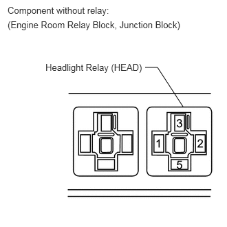
2.198,1.021 2.385,1.021 2.385,1.021 2.771,1.615 false 0.115,0.073 2.521,0.323 2.406,0.25 10 false Component without relay: 0.688,0.938 2.229,1.177 1.542,0.24 10 false Headlight Relay (HEAD) 0.115,0.292 2.833,0.542 2.719,0.25 10 false (Engine Room Relay Block, Junction Block)

a.

Remove the headlight relay from the engine room relay block.


b.

Measure the voltage according to the value(s) in the table below.

Standard voltage:
Tester Connection Condition Specified Condition
Headlight dimmer relay terminal 1 - Body ground Always 11 to 14 V
Headlight dimmer relay terminal 3 - Body ground


OK

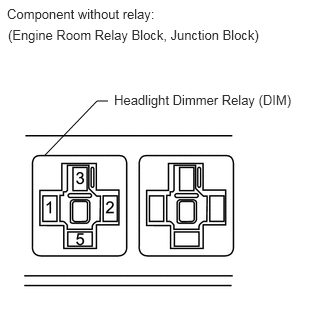
6.INSPECT HEADLIGHT DIMMER RELAY (DIM)

NG

REPAIR OR REPLACE HARNESS OR CONNECTOR

6.INSPECT HEADLIGHT DIMMER RELAY (DIM)
E277741E03
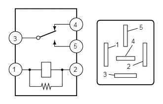
2.417,1.583 2.292,1.563 false 3.01,1.292 2.802,1.375 false 2.646,1.177 2.792,0.948 false 2.688,0.656 2.906,0.594 false 2.281,1.01 2.438,0.958 false 0.26,1.375 0.427,1.563 0.167,0.188 10 false 1 1.552,1.375 1.719,1.563 0.167,0.188 10 false 2 0.281,0.729 0.448,0.917 0.167,0.188 10 false 3 1.552,0.438 1.719,0.625 0.167,0.188 10 false 4 1.552,0.885 1.719,1.073 0.167,0.188 10 false 5 2.438,0.854 2.604,1.042 0.167,0.188 10 false 1 2.677,1.313 2.844,1.5 0.167,0.188 10 false 2 2.177,1.479 2.344,1.667 0.167,0.188 10 false 3 2.771,0.781 2.938,0.969 0.167,0.188 10 false 4 2.938,0.49 3.104,0.677 0.167,0.188 10 false 5

a.

Remove the headlight dimmer relay from the engine room relay block.


b.

Measure the resistance according to the value(s) in the table below.

Standard resistance:
Tester Connection Condition Specified Condition
3 - 5 Battery voltage not applied to terminals 1 and 2 10 kΩ or higher
Battery voltage applied to terminals 1 and 2 Below 1 Ω
3 - 4 Battery voltage not applied to terminals 1 and 2 Below 1 Ω
Battery voltage applied to terminals 1 and 2 10 kΩ or higher


OK

7.CHECK HARNESS AND CONNECTOR (HEADLIGHT DIMMER RELAY [DIM] - BATTERY)

NG

REPLACE HEADLIGHT DIMMER RELAY

7.CHECK HARNESS AND CONNECTOR (HEADLIGHT DIMMER RELAY [DIM] - BATTERY)
E344840E02
0.469,1.615 1.01,1.052 1.01,1.052 1.125,1.052 false 0.073,0.063 2.458,0.302 2.385,0.24 10 false Component without relay: 1.188,0.958 3.146,1.208 1.958,0.25 10 false Headlight Dimmer Relay (DIM) 0.083,0.281 3.094,0.698 3.01,0.417 10 false (Engine Room Relay Block, Junction Block)

a.

Remove the headlight relay from the engine room relay block.


b.

Measure the voltage according to the value(s) in the table below.

Standard voltage:
Tester Connection Condition Specified Condition
Headlight relay terminal 1 - Body ground Light control switch HEAD, dimmer switch Low 11 to 14 V
Headlight relay terminal 3 - Body ground Light control switch HEAD, dimmer switch Low


OK

8.CHECK HARNESS AND CONNECTOR (HEADLIGHT RELAY [HEAD] - HEADLIGHT DIMMER RELAY [DIM])

NG

REPAIR OR REPLACE HARNESS OR CONNECTOR

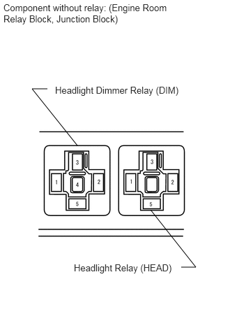
8.CHECK HARNESS AND CONNECTOR (HEADLIGHT RELAY [HEAD] - HEADLIGHT DIMMER RELAY [DIM])
E282218E03
1.156,2.167 0.479,1.323 0.479,1.323 0.708,1.323 false 2.25,3.125 2.927,3.979 2.927,3.979 2.708,3.979 false 0.052,0.031 2.771,0.802 2.719,0.771 10 false Component without relay: (Engine Room Relay Block, Junction Block) 0.823,1.26 2.75,1.625 1.927,0.365 10 false Headlight Dimmer Relay (DIM) 1.104,3.906 2.667,4.292 1.563,0.385 10 false Headlight Relay (HEAD)

a.

Remove the headlight relay from the engine room relay block.


b.

Remove the headlight dimmer relay from the engine room relay block.


c.

Measure the resistance according to the value(s) in the table below.

Standard resistance:
Tester Connection Condition Specified Condition
Headlight relay terminal 5 - Headlight dimmer relay terminal 3 Always Below 1 Ω
Headlight relay terminal 5 - Body ground Always 10 kΩ or higher
Headlight dimmer relay terminal 3 - Body ground Always 10 kΩ or higher
Headlight relay terminal 5 - Headlight dimmer relay terminal 1 Always Below 1 Ω
Headlight dimmer relay terminal 1- Body ground Always 10 kΩ or higher


OK

9.CHECK HARNESS AND CONNECTOR (HEADLIGHT DIMMER RELAY [DIM] - HEADLIGHT LOW BULB)

NG

REPAIR OR REPLACE HARNESS OR CONNECTOR

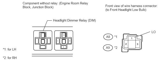
9.CHECK HARNESS AND CONNECTOR (HEADLIGHT DIMMER RELAY [DIM] - HEADLIGHT LOW BULB)
U152900E02
1.865,1.323 2.042,0.885 2.042,0.885 2.24,0.885 false 5.802,1.615 6.479,1.365 true 0.979,0.052 3.927,0.708 2.948,0.656 10 false Component without relay: (Engine Room Relay Block, Junction Block) 2.292,0.792 4.24,1.135 1.948,0.344 10 false Headlight Dimmer Relay (DIM) 4.552,0.167 6.938,0.833 2.385,0.667 10 false Front view of wire harness connector: (to Front Headlight Low Bulb) 4.938,1.5 5.219,1.656 0.281,0.156 10 false *1 4.938,1.969 5.219,2.125 0.281,0.156 10 false *2 4.583,1.5 4.865,1.656 0.281,0.156 10 false A8 4.573,1.969 4.854,2.125 0.281,0.156 10 false A9 0.125,2.042 0.76,2.333 0.635,0.292 10 false *1: for LH 0.125,2.406 0.792,2.719 0.667,0.313 10 false *2: for RH 6.542,1.292 6.771,1.49 0.229,0.198 10 false LO

*1: for LH

*2: for RH

a.

Remove the headlight dimmer relay from the engine room relay block.


b.

Disconnect the A8*1 and A9*2 headlight connectors.


c.

Measure the resistance according to the value(s) in the table below.

Standard resistance:
Tester Connection Condition Specified Condition
Headlight dimmer relay terminal 4 - A8-1 (LO)*1 Always Below 1 Ω
Headlight dimmer relay terminal 4 - Body ground*1 Always 10 kΩ or higher
Headlight dimmer relay terminal 4 - A9-1 (LO)*2 Always Below 1 Ω
Headlight dimmer relay terminal 4 - Body ground*2 Always 10 kΩ or higher


OK

10.CHECK HEADLIGHT (LOW BEAM)

NG

REPAIR OR REPLACE HARNESS OR CONNECTOR

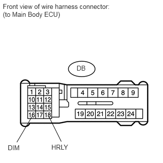
10.CHECK HEADLIGHT (LOW BEAM)
U152775E01
0.06,0.049 2.445,0.399 2.385,0.350 10 Front view of wire harness connector: (to Main Body ECU) 1.615,1.355 1.841,1.511 0.225,0.156 10 DB 1.084,3.016 1.484,3.165 0.400,0.149 10 HRLY 1.292,2.985 1.031,2.458 false 0.355,2.999 0.671,2.463 false 0.164,3.036 0.481,3.185 0.317,0.149 10 DIM

a.

Disconnect the DB ECU connector.


b.

Using a service wire, connect DB-18 (HRLY) and DB-16 (DIM) on the wire harness side and body ground.


c.

Check that the headlight low beam illuminates.

OK:

Headlight low beam illuminates.


OK

REPLACE MAIN BODY ECU

NG

REPAIR OR REPLACE HARNESS OR CONNECTOR