Home › Vehicle Interior › LIGHTING › LIGHTING SYSTEM
RM27M0U _58 Vehicle Interior _049133 LIGHTING _0234252 LIGHTING SYSTEM J

LIGHTING  LIGHTING SYSTEM  DRL Relay Circuit  


DESCRIPTION

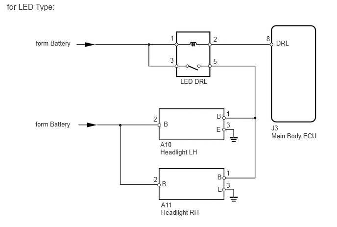
The main body ECU controls the daytime running lights.

WIRING DIAGRAM
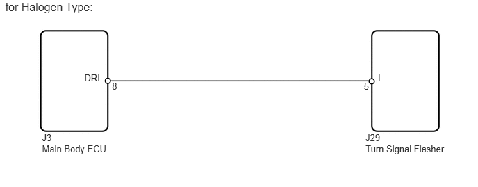
E146735E03
0.63,2.151 1.712,2.334 1.082,0.184 10 Main Body ECU 0.63,1.984 0.934,2.158 0.304,0.174 10 J3 5.48,2.151 6.757,2.334 1.276,0.184 10 Turn Signal Flasher 5.48,1.984 5.784,2.158 0.304,0.174 10 J29 1.265,1.088 1.587,1.291 0.323,0.202 10 DRL 5.668,1.088 5.990,1.291 0.323,0.202 10 L 1.679,1.212 1.815,1.366 0.136,0.154 10 8 5.455,1.212 5.592,1.366 0.136,0.154 10 5 0.079,0.002 1.457,0.213 1.378,0.211 12 for Halogen Type:

E282159E01
5.77,2.798 6.852,2.981 1.082,0.184 10 Main Body ECU 5.77,2.631 6.074,2.805 0.304,0.174 10 J3 5.873,0.829 6.195,1.031 0.323,0.202 10 DRL 3.48,2.557 3.803,2.759 0.323,0.202 10 B 4.54,0.748 4.676,0.901 0.136,0.154 10 2 4.536,1.217 4.672,1.371 0.136,0.154 10 5 0.147,0.041 1.525,0.253 1.378,0.211 12 for LED Type: 3.836,1.643 4.465,1.813 0.628,0.170 10 LED DRL 3.622,0.727 3.758,0.880 0.136,0.154 10 1 3.618,1.196 3.755,1.350 0.136,0.154 10 3 4.608,2.389 4.931,2.591 0.323,0.202 10 B 3.445,3.818 3.768,4.020 0.323,0.202 10 B 4.622,3.678 4.945,3.880 0.323,0.202 10 B 4.601,2.662 4.924,2.864 0.323,0.202 10 E 4.629,3.937 4.952,4.139 0.323,0.202 10 E 0.761,0.831 1.584,1.007 0.823,0.177 10 form Battery 3.409,3.149 4.287,3.319 0.878,0.170 10 Headlight LH 3.409,2.988 3.713,3.163 0.304,0.174 10 A10 3.423,4.431 4.301,4.601 0.878,0.170 10 Headlight RH 3.423,4.27 3.727,4.445 0.304,0.174 10 A11 5.664,0.741 5.800,0.894 0.136,0.154 10 8 3.272,3.732 3.408,3.886 0.136,0.154 10 2 4.813,3.592 4.949,3.745 0.136,0.154 10 1 4.816,2.569 4.953,2.723 0.136,0.154 10 3 3.265,2.45 3.401,2.604 0.136,0.154 10 2 4.813,2.331 4.949,2.484 0.136,0.154 10 1 4.816,3.858 4.953,4.012 0.136,0.154 10 3 0.754,2.554 1.577,2.731 0.823,0.177 10 form Battery

CAUTION / NOTICE / HINT

HINT:

Inspect the headlights for circuits related to this system before performing the following inspection procedure.


PROCEDURE

1.CHECK VEHICLE TYPE
a.

Check vehicle type.

Result
Result Proceed to
for Halogen Type A
for LED Type B


A

2.CHECK HARNESS AND CONNECTOR (TURN SIGNAL FLASHER - MAIN BODY ECU)

B

4.CHECK HARNESS AND CONNECTOR (HEADLIGHT - BATTERY)
2.CHECK HARNESS AND CONNECTOR (TURN SIGNAL FLASHER - MAIN BODY ECU)
U152770E02
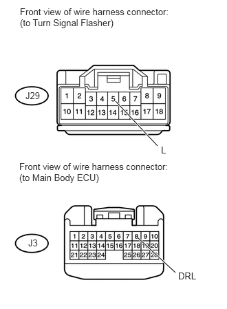
1.75,1.531 2.385,2.208 true 2.094,3.604 2.656,4.125 true 0.302,0.094 2.604,0.719 2.302,0.625 10 false Front view of wire harness connector: (to Turn Signal Flasher) 0.292,2.438 2.656,3.052 2.365,0.615 10 false Front view of wire harness connector: (to Main Body ECU) 0.385,1.365 0.646,1.531 0.26,0.167 10 false J29 0.427,3.594 0.625,3.76 0.198,0.167 10 false J3 2.438,2.188 2.75,2.365 0.313,0.177 10 false L 2.698,4.094 3.01,4.271 0.313,0.177 10 false DRL

a.

Disconnect the J29 relay connector.


b.

Disconnect the J3 ECU connector.


c.

Measure the resistance according to the value(s) in the table below.

Standard resistance:
Tester Connection Condition Specified Condition
J29-5 (L) - J3-8 (DRL) Always Below 1 Ω
J29-5 (L) - Body ground Always 10 kΩ or higher


OK

3.CHECK MAIN BODY ECU

NG

REPAIR OR REPLACE HARNESS OR CONNECTOR

3.CHECK MAIN BODY ECU
E146750E02
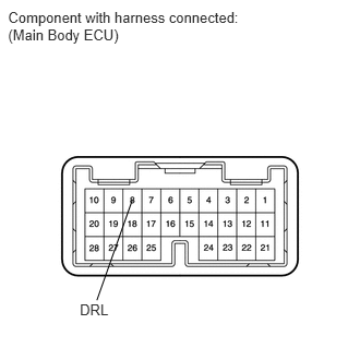
0.077,0.082 2.418,0.437 2.341,0.355 10 Component with harness connected: (Main Body ECU) 0.762,2.875 1.071,3.026 0.309,0.151 10 DRL 0.925,2.866 1.263,1.909 false

a.

Disconnect the J29 relay connector.


b.

Measure the voltage according to the value(s) in the table below.

Standard voltage:
Tester Connection Switch Condition Specified Condition
8 (DRL) - Body ground Ignition switch ON 11 to 14 V
Ignition switch OFF Below 1 V


OK

PROCEED TO NEXT CIRCUIT INSPECTION SHOWN IN PROBLEM SYMPTOMS TABLE

NG

REPLACE MAIN BODY ECU

4.CHECK HARNESS AND CONNECTOR (HEADLIGHT - BATTERY)
U152910E02
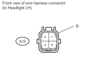
1.896,1.229 2.594,0.917 true 0.667,1.375 0.969,1.521 0.302,0.146 10 false A10 2.667,0.833 2.802,0.99 0.135,0.156 10 false B 0.083,0.021 2.427,0.635 2.344,0.615 10 false Front view of wire harness connector: (to Headlight LH)

a.

for LH:

i.

Disconnect the A10 headlight connector.


ii.

Measure the voltage according to the value(s) in the table below.

Standard voltage:
Tester Connection Switch Condition Specified Condition
A10-1 (B) - Body ground Light control switch TAIL 11 to 14 V
Light control switch except TAIL Below 1 V
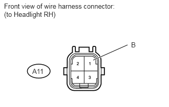


U152911E02
1.896,1.229 2.594,0.917 true 0.656,1.375 0.958,1.521 0.302,0.146 10 false A11 2.667,0.833 2.802,0.99 0.135,0.156 10 false B 0.083,0.042 2.448,0.667 2.365,0.625 10 false Front view of wire harness connector: (to Headlight RH)

b.

for RH:

i.

Disconnect the A11 headlight connector.


ii.

Measure the voltage according to the value(s) in the table below.

Standard voltage:
Tester Connection Switch Condition Specified Condition
A11-1 (B) - Body ground Light control switch TAIL 11 to 14 V
Light control switch except TAIL Below 1 V


OK

REPAIR OR REPLACE HARNESS OR CONNECTOR (HEADLIGHT - BODY GROUND)

NG

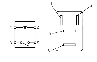
5.INSPECT DAYTIME RUNNING LIGHT RELAY (LED DRL)
a.
E121182E14
1.724,1.093 1.835,1.242 0.111,0.149 10 5 1.779,0.046 1.889,0.194 0.111,0.149 10 1 3.197,0.107 3.308,0.256 0.111,0.149 10 2 1.69,1.712 1.800,1.860 0.111,0.149 10 3 0.349,1.428 0.460,1.577 0.111,0.149 10 3 1.299,0.878 1.409,1.027 0.111,0.149 10 2 0.353,0.874 0.464,1.023 0.111,0.149 10 1 1.307,1.424 1.418,1.573 0.111,0.149 10 5 1.862,1.183 2.269,1.084 false 2.269,1.583 1.806,1.785 false 2.14,0.624 1.857,0.225 false 2.764,0.533 3.168,0.242 false

Remove the daytime running light relay from the engine room relay block.


b.

Measure the resistance according to the value(s) in the table below.


Standard resistance:
Tester Connection Condition Specified Condition
3 - 5 When battery voltage is applied to terminals 1 and 2 Below 1 Ω
3 - 5 When battery voltage is not applied to terminals 1 and 2 10 kΩ or higher


OK

6.CHECK HARNESS AND CONNECTOR (DAYTIME RUNNING LIGHT RELAY [LED DRL] - BATTERY)

NG

REPLACE DAYTIME RUNNING LIGHT RELAY (LED DRL)

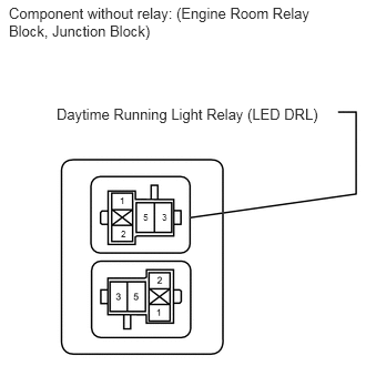
6.CHECK HARNESS AND CONNECTOR (DAYTIME RUNNING LIGHT RELAY [LED DRL] - BATTERY)
U152778E02
0.083,0.042 2.927,0.833 2.844,0.792 10 false Component without relay: (Engine Room Relay Block, Junction Block) 1.125,1.833 1.292,1.979 0.167,0.146 6 false 1 1.135,2.146 1.302,2.292 0.167,0.146 6 false 2 1.521,1.99 1.688,2.135 0.167,0.146 6 false 3 1.344,1.99 1.51,2.135 0.167,0.146 6 false 5 0.531,0.99 3.104,1.354 2.573,0.365 10 false Daytime Running Light Relay (LED DRL)

a.

Remove the daytime running light relay from the engine room relay block.


b.

Measure the voltage according to the value(s) in the table below.

Standard voltage:
Tester Connection Condition Specified Condition
Daytime running light relay terminal 1 - Body ground Always 11 to 14 V
Daytime running light relay terminal 3 - Body ground


OK

7.CHECK HARNESS AND CONNECTOR (DAYTIME RUNNING LIGHT RELAY [LED DRL] - HEADLIGHT)

NG

REPAIR OR REPLACE HARNESS OR CONNECTOR

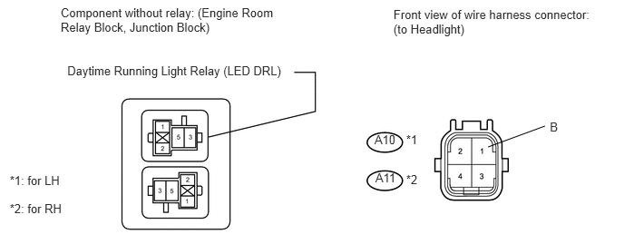
7.CHECK HARNESS AND CONNECTOR (DAYTIME RUNNING LIGHT RELAY [LED DRL] - HEADLIGHT)
U152909E01
0.697,0.061 3.261,0.437 2.564,0.376 10 Component without relay: (Engine Room Relay Block, Junction Block) 4.519,0.079 6.855,0.455 2.335,0.376 10 Front view of wire harness connector: (to Headlight) 4.301,1.52 4.585,1.686 0.284,0.166 10 A10 6.315,1.377 6.630,1.554 0.316,0.177 10 B 5.605,1.687 6.258,1.447 false 0.773,0.725 3.332,0.916 2.559,0.191 10 Daytime Running Light Relay (LED DRL) 4.311,1.959 4.595,2.125 0.284,0.166 10 A11 4.665,1.521 4.835,1.691 0.170,0.170 10 *1 4.665,1.984 4.835,2.153 0.170,0.170 10 *2 0.112,1.993 0.749,2.163 0.637,0.170 10 *1: for LH 0.112,2.315 0.754,2.485 0.642,0.170 10 *2: for RH

*1: for LH

*2: for RH


a.

Remove the daytime running light relay from the engine room relay block.


b.

Disconnect the A10*1 and A11*2 headlight connectors.


c.

Measure the resistance according to the value(s) in the table below.

Standard resistance:
Tester Connection Condition Specified Condition
Daytime running light relay terminal 5 - A10-1 (B)*1 Always Below 1 Ω
Daytime running light relay terminal 5 - Body ground*1 Always 10 kΩ or higher
Daytime running light relay terminal 5 - A11-1 (B)*2 Always Below 1 Ω
Daytime running light relay terminal 5 - Body ground*2 Always 10 kΩ or higher


OK

8.CHECK HARNESS AND CONNECTOR (DAYTIME RUNNING LIGHT RELAY [LED DRL] - MAIN BODY ECU)

NG

REPAIR OR REPLACE HARNESS OR CONNECTOR

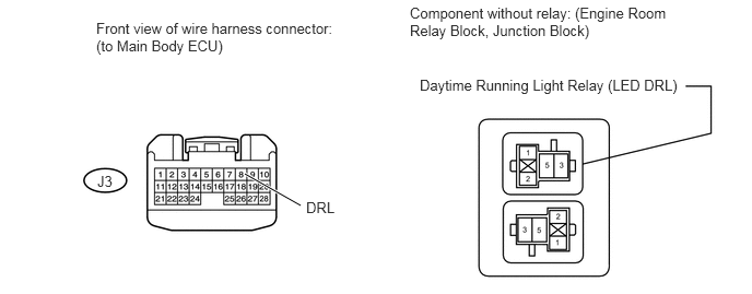
8.CHECK HARNESS AND CONNECTOR (DAYTIME RUNNING LIGHT RELAY [LED DRL] - MAIN BODY ECU)
U152888E02
2.333,1.656 2.865,1.958 true 3.906,0.042 6.51,0.677 2.604,0.635 10 false Component without relay: (Engine Room Relay Block, Junction Block) 0.917,0.188 3.229,0.844 2.313,0.656 10 false Front view of wire harness connector: (to Main Body ECU) 0.927,1.646 1.125,1.813 0.198,0.167 10 false J3 2.917,1.896 3.229,2.073 0.313,0.177 10 false DRL 4,0.729 6.521,1.083 2.521,0.354 10 false Daytime Running Light Relay (LED DRL)

a.

Remove the daytime running light relay from the engine room relay block.


b.

Disconnect the J3 ECU connector.


c.

Measure the resistance according to the value(s) in the table below.

Standard resistance:
Tester Connection Condition Specified Condition
Daytime running light relay terminal 2 - J3-8 (DRL) Always Below 1 Ω
J3-8 (DRL) - Body ground Always 10 kΩ or higher


OK

REPLACE MAIN BODY ECU

NG

REPAIR OR REPLACE HARNESS OR CONNECTOR