Home › Vehicle Interior › LIGHTING › LIGHTING SYSTEM
RM27M0U _58 Vehicle Interior _049133 LIGHTING _0234252 LIGHTING SYSTEM J

LIGHTING  LIGHTING SYSTEM  Cargo Light Circuit  


DESCRIPTION

The main body ECU receives a cargo light information signal from the cargo light switch and door courtesy light switch, and illuminates the cargo light.

WIRING DIAGRAM
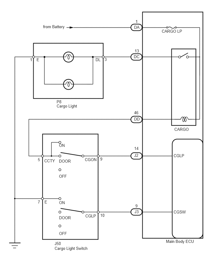
E147662E03
5.718,8.224 6.795,8.406 1.077,0.182 10 Main Body ECU 5.979,7.212 6.617,7.391 0.637,0.178 10 CGSW 5.979,5.274 6.501,5.453 0.522,0.179 10 CGLP 4.662,7.002 4.874,7.165 0.212,0.163 10 9 4.618,3.791 4.824,3.955 0.205,0.164 10 46 4.618,4.007 4.863,4.171 0.245,0.164 10 DD 4.622,5.024 4.848,5.195 0.225,0.171 10 14 3.453,7.319 3.655,7.499 0.202,0.180 10 10 3.45,5.381 3.646,5.551 0.195,0.169 10 9 4.634,7.201 4.833,7.364 0.198,0.163 10 J3 4.622,5.257 4.848,5.427 0.225,0.171 10 J2 2.922,5.406 3.371,5.568 0.449,0.162 10 CGON 2.939,7.344 3.349,7.513 0.410,0.169 10 CGLP 1.524,5.446 1.952,5.608 0.427,0.162 10 CCTY 1.533,6.862 1.693,7.024 0.160,0.162 10 E 1.302,6.862 1.462,7.024 0.160,0.162 10 7 1.302,5.403 1.462,5.565 0.160,0.162 10 5 2.031,4.919 2.302,5.081 0.270,0.162 10 ON 2.031,5.456 2.520,5.618 0.488,0.162 10 DOOR 2.031,5.978 2.352,6.140 0.321,0.162 10 OFF 2.033,6.883 2.325,7.045 0.291,0.162 10 ON 2.033,7.406 2.561,7.568 0.528,0.162 10 DOOR 2.033,7.944 2.380,8.107 0.346,0.162 10 OFF 1.88,8.295 2.222,8.457 0.341,0.162 10 J50 1.88,8.458 3.151,8.619 1.270,0.162 10 Cargo Light Switch 1.95,3.56 2.710,3.709 0.760,0.149 10 Cargo Light 1.95,3.42 2.203,3.569 0.253,0.149 10 P8 3.292,1.973 3.545,2.122 0.253,0.149 10 DL 1.26,1.973 1.513,2.122 0.253,0.149 10 E 1.033,1.973 1.286,2.122 0.253,0.149 10 1 3.6,1.963 3.853,2.112 0.253,0.149 10 3 6.006,4.362 6.801,4.511 0.795,0.149 10 CARGO 5.572,0.986 6.367,1.134 0.795,0.149 10 CARGO LP 4.617,0.854 4.838,1.000 0.220,0.145 10 DA 4.668,0.655 4.803,0.800 0.135,0.145 10 1 1.486,0.835 2.281,1.005 0.795,0.170 10 from Battery 4.609,1.868 4.837,2.021 0.229,0.152 10 DC 4.637,1.662 4.866,1.814 0.229,0.152 10 13

CAUTION / NOTICE / HINT

HINT:

Inspect the bulbs for circuits related to this system before performing the following inspection procedure.


PROCEDURE

1.INSPECT FUSE (CARGO)
a.

Remove the CARGO LP fuse from the main body ECU.


b.

Measure the resistance according to the value(s) in the table below.

Standard resistance:
Tester Connection Condition Specified Condition
CARGO LP fuse Always Below 1 Ω


OK

2.PERFORM ACTIVE TEST USING TECHSTREAM (CARGO LIGHT)

NG

REPLACE FUSE

2.PERFORM ACTIVE TEST USING TECHSTREAM (CARGO LIGHT)
a.

Operate the Techstream according to the steps on the display and select "Active Test".

Main Body ECU
Tester Display Test Part Control Range Diagnostic Note
Cargo Light Cargo light ON or OFF Cargo light switch is DOOR or on

OK:

Cargo light turns on / turns off.


OK

PROCEED TO NEXT CIRCUIT INSPECTION SHOWN IN PROBLEM SYMPTOMS TABLE

NG

3.READ VALUE USING TECHSTREAM (CARGO LIGHT SWITCH)
a.

Operate the Techstream according to the display and select the "Data List".

Main Body ECU
Tester Display Measurement Item/Range Normal Condition Diagnostic Note
Cargo Light Switch Cargo light switch signal / ON or OFF ON: Cargo light switch on
OFF: Cargo light switch off
-

OK:

When cargo light switch operation is performed, the results are the same as above.


OK

4.CHECK HARNESS AND CONNECTOR (CARGO LIGHT - BATTERY AND BODY GROUND)

NG

5.INSPECT CARGO LIGHT SWITCH
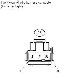
4.CHECK HARNESS AND CONNECTOR (CARGO LIGHT - BATTERY AND BODY GROUND)
U152726E01
0.042,0.025 2.469,0.368 2.427,0.343 10 Front view of wire harness connector: (to Cargo Light) 1.632,1.331 1.830,1.477 0.198,0.145 10 P8 2.431,3.011 2.632,3.164 0.201,0.152 10 DL 0.88,3.011 1.081,3.164 0.201,0.152 10 E 2.515,3.011 2.05,2.455 false 0.975,2.981 1.412,2.466 false

a.

Disconnect the P8 light connector.


b.

Measure the voltage according to the value(s) in the table below.

Standard voltage:
Tester Connection Switch Condition Specified Condition
P8-3 (DL) - Body ground Cargo light switch ON 11 to 14 V
Cargo light switch DOOR, door is open
Cargo light switch OFF Below 1 V


c.

Measure the resistance according to the value(s) in the table below.

Standard resistance:
Tester Connection Switch Condition Specified Condition
P8-1 (E) - Body ground Always Below 1 Ω


OK

REPLACE MAIN BODY ECU

NG

REPAIR OR REPLACE HARNESS OR CONNECTOR

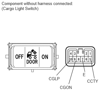
5.INSPECT CARGO LIGHT SWITCH
E143954E02
1.624,2.537 2.020,2.689 0.395,0.152 10 CGLP 1.995,2.829 2.451,2.981 0.456,0.152 10 CGON 2.906,2.627 3.329,2.779 0.423,0.152 10 CCTY 2.763,2.408 2.905,2.560 0.142,0.152 10 E 2.751,2.008 2.833,2.399 false 2.348,2.004 1.886,2.515 false 3.033,2.012 3.15,2.621 false 2.522,2.025 2.295,2.802 false 0.053,0.029 2.524,0.388 2.471,0.360 10 Component without harness connected: (Cargo Light Switch)

a.

Remove the cargo light switch (see page Vehicle Interior>LIGHTING>CARGO LIGHT SWITCH>REMOVAL).


b.

Measure the resistance according to the value(s) in the table below.

Standard resistance:
Tester Connection Switch Condition Specified Condition
5 (CCTY) - 9 (CGON) Cargo light switch ON Below 1 Ω
Cargo light switch DOOR
Cargo light switch OFF 10 kΩ or higher
10 (CGLP) - 7 (E) Cargo light switch ON Below 1 Ω
Cargo light switch DOOR 10 kΩ or higher
Cargo light switch OFF


OK

6.CHECK HARNESS AND CONNECTOR (CARGO LIGHT SWITCH - MAIN BODY ECU)

NG

REPLACE CARGO LIGHT SWITCH

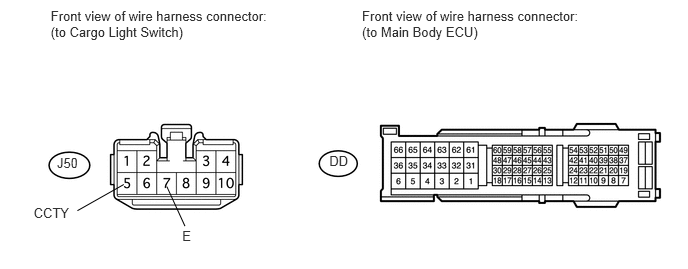
6.CHECK HARNESS AND CONNECTOR (CARGO LIGHT SWITCH - MAIN BODY ECU)
U152912E01
0.528,0.081 2.887,0.422 2.360,0.341 10 Front view of wire harness connector: (to Cargo Light Switch) 0.593,1.612 0.860,1.777 0.267,0.165 10 J50 1.289,1.921 0.806,2.194 false 1.737,1.942 1.926,2.355 false 0.35,2.131 0.770,2.300 0.420,0.170 10 CCTY 1.898,2.376 2.033,2.546 0.135,0.170 10 E 3.771,0.081 6.131,0.422 2.360,0.341 10 Front view of wire harness connector: (to Main Body ECU) 3.43,1.598 3.697,1.763 0.267,0.165 10 DD

a.

Disconnect the J50 cargo light switch connector.


b.

Disconnect the DD ECU connector.


c.

Measure the resistance according to the value(s) in the table below.

Standard resistance:
Tester Connection Switch Condition Specified Condition
J50-5 (CCTY) - DD-46 Always Below 1 Ω
J50-7 (E) - Body ground
J50-5 (CCTY) - Body ground Always 10 kΩ or higher


OK

7.CHECK HARNESS AND CONNECTOR (MAIN BODY ECU - BATTERY AND BODY GROUND)

NG

REPAIR OR REPLACE HARNESS OR CONNECTOR

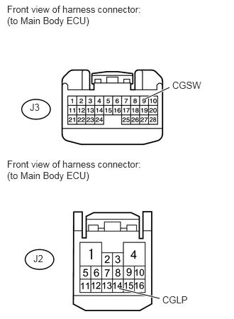
7.CHECK HARNESS AND CONNECTOR (MAIN BODY ECU - BATTERY AND BODY GROUND)
U152800E02
2.135,1.448 2.49,1.281 true 1.75,4.229 2.344,4.375 true 0.104,2.323 2.188,2.635 2.083,0.313 10 false Front view of harness connector: (to Main Body ECU) 0.438,1.49 0.615,1.646 0.177,0.156 10 false J3 0.104,0.052 2.188,0.365 2.083,0.313 10 false Front view of harness connector: (to Main Body ECU) 0.49,3.708 0.667,3.865 0.177,0.156 10 false J2 2.531,1.167 3,1.313 0.469,0.146 10 false CGSW 2.385,4.313 2.823,4.458 0.438,0.146 10 false CGLP

a.

Disconnect the J2 and J3 ECU connectors.


b.

Measure the voltage according to the value(s) in the table below.

Standard voltage:
Tester Connection Switch Condition Specified Condition
J2-14 (CGLP) - Body ground Cargo light switch ON or DOOR 11 to 14 V
Cargo light switch OFF Below 1 V


c.

Measure the resistance according to the value(s) in the table below.

Standard resistance:
Tester Connection Switch Condition Specified Condition
J3-9 (CGSW) - Body ground Cargo light switch ON Below 1 Ω
Cargo light switch DOOR or OFF 10 kΩ or higher


OK

REPLACE MAIN BODY ECU

NG

REPAIR OR REPLACE HARNESS OR CONNECTOR