RM27M0U
_58
Vehicle Interior
_049136
SEAT
_0234304
FRONT POWER SEAT CONTROL SYSTEM(w/ Memory)
U
SEAT FRONT POWER SEAT CONTROL SYSTEM(w/ Memory) TERMINALS OF ECU
CHECK POSITION CONTROL ECU AND SWITCH ASSEMBLY

3.167,0.292 3.365,0.458
0.198,0.167
10
false
Z9
4.115,0.292 4.365,0.479
0.25,0.188
10
false
Z10
a.
Disconnect the Z9 and Z10 position control ECU and switch assembly connectors.
b.
Measure the voltage and resistance according to the value(s) in the table below.
| Terminal No. (Symbols) | Wiring Color | Terminal Description | Condition | Specified Condition |
|---|---|---|---|---|
| Z9-2 (GND1) - Body ground | W-B - Body ground | Ground | Always | Below 1 Ω |
| Z9-7 (+B1) - Z9-2 (GND1) | W - W-B | Battery (ECU power source) | Always | 11 to 14 V |
| Z10-12 (SYSB) - Z9-2 (GND1) | LG - W-B | Battery (ECU power source) | Always | 11 to 14 V |
| Z10-10 (DBCL) - Z10-1 (SGND) | P - BR | Front seat inner belt buckle switch signal | Seat belt unfastened | Below 1 Ω |
| Seat belt fastened | 10 kΩ or higher |
c.
Reconnect the Z9 and Z10 position control ECU and switch assembly connectors.
d.
Measure the voltage and resistance according to the value(s) in the table below.
| Terminal No. (Symbols) | Wiring Color | Terminal Description | Condition | Specified Condition |
|---|---|---|---|---|
| Z9-1 (GND2) - Body ground | W-B - Body ground | Lumbar support adjuster ground | Always | Below 1 Ω |
| Z9-3 (SLD+) - Z9-2 (GND1) | L - W-B | Sliding motor signal (forward) | Seat moving forward using sliding switch | 11 to 14 V |
| OFF | Below 1 V | |||
| Z9-4 (SLD-) - Z9-2 (GND1) | GR - W-B | Sliding motor signal (rearward) | Seat moving rearward using sliding switch | 11 to 14 V |
| OFF | Below 1 V | |||
| Z9-5 (FRV-) - Z9-2 (GND1) | R - W-B | Front Vertical motor signal (downward) | Seat cushion front portion downward using front vertical switch | 11 to 14 V |
| OFF | Below 1 V | |||
| Z9-6 (+B2) - Z9-1 (GND2) | LG - W-B | Lumbar support adjuster power source | Always | 11 to 14 V |
| Z9-8 (FRV+) - Z9-2 (GND1) | B - W-B | Front vertical motor signal (upward) | Seat cushion front portion upward using front vertical switch | 11 to 14 V |
| OFF | Below 1 V | |||
| Z9-9 (RCL+) - Z9-2 (GND1) | LG - W-B | Reclining motor signal (forward) | Seatback moving forward using reclining switch | 11 to 14 V |
| OFF | Below 1 V | |||
| Z9-10 (LFT+) - Z9-2 (GND1) | V - W-B | Lift or motor signal (upward) | Seat cushion upward using lifter switch | 11 to 14 V |
| OFF | Below 1 V | |||
| Z9-11 (RCL-) - Z9-2 (GND1) | P - W-B | Reclining motor signal (rearward) | Seatback moving rearward using reclining switch | 11 to 14 V |
| OFF | Below 1 V | |||
| Z9-12 (LFT-) - Z9-2 (GND1) | Y - W-B | Lift or motor signal (downward) | Seat cushion downward using lifter switch | 11 to 14 V |
| OFF | Below 1 V | |||
| Z10-1 (SGND) - Body ground | BR - Body ground | Position sensor ground | Always | Below 1 Ω |
| Z10-3 (SSFV) - Z10-1 (SGND) | R - BR | Vertical position signal | Front vertical function operation | 4.5 to 4.8 V |
| Z10-4 (SSRL) - Z10-1 (SGND) | P - BR | Lift position signal | Lifter function operation | 4.5 to 4.8 V |
| Z10-5 (SSRS) - Z10-1 (SGND) | G - BR | Slide position signal | Slide function operation | 4.5 to 4.8 V |
| Z10-11 (SSRR) - Z10-1 (SGND) | O - BR | Reclining position signal | Reclining function operation | 4.5 to 4.8 V |
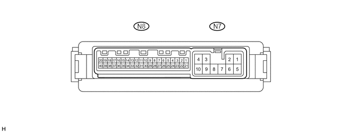
CHECK OUTER MIRROR CONTROL ECU ASSEMBLY
4.469,0.469 4.667,0.646
0.198,0.177
10
false
N7
2.875,0.469 3.073,0.646
0.198,0.177
10
false
N8
a.
Disconnect the N7 outer mirror control ECU assembly connector.
b.
Measure the voltage and resistance according to the value(s) in the table below.
| Terminal No. (Symbols) | Wiring Color | Terminal Description | Condition | Specified Condition |
|---|---|---|---|---|
| N7-3 (B) - N7-9 (GND) | R - W-B | Battery (ECU power source) | Always | 11 to 14 V |
| N7-4 (ACC) - N7-9 (GND) | Y - W-B | Ignition power supply | Ignition switch off | Below 1 V |
| Ignition switch ACC | 11 to 14 V | |||
| N7-9 (GND) - Body ground | W-B - Body ground | Ground | Always | Below 1 Ω |
c.
Reconnect the N7 outer mirror control ECU assembly connector.
d.
Measure the voltage according to the value(s) in the table below.
| Terminal No. (Symbols) | Wiring Color | Terminal Description | Condition | Specified Condition |
|---|---|---|---|---|
| N8-7 (M2) - N8-10 (MSWE) | BE - V | Memory 2 switch signal | Memory 2 switch off | 11 to 14 V |
| Memory 2 switch on | Below 1 V | |||
| N8-8 (M1) - N8-10 (MSWE) | P - V | Memory 1 switch signal | Memory 1 switch off | 11 to 14 V |
| Memory 1 switch on | Below 1 V | |||
| N8-9 (MM) - N8-10 (MSWE) | L - V | Memory SET switch signal | Memory SET switch off | 11 to 14 V |
| Memory SET switch on | Below 1 V |