Home › Vehicle Interior › DOOR LOCK › POWER DOOR LOCK CONTROL SYSTEM
RM27M0U _58 Vehicle Interior _049137 DOOR LOCK _0234324 POWER DOOR LOCK CONTROL SYSTEM J

DOOR LOCK  POWER DOOR LOCK CONTROL SYSTEM  Driver Side Door Lock Motor Circuit  


DESCRIPTION

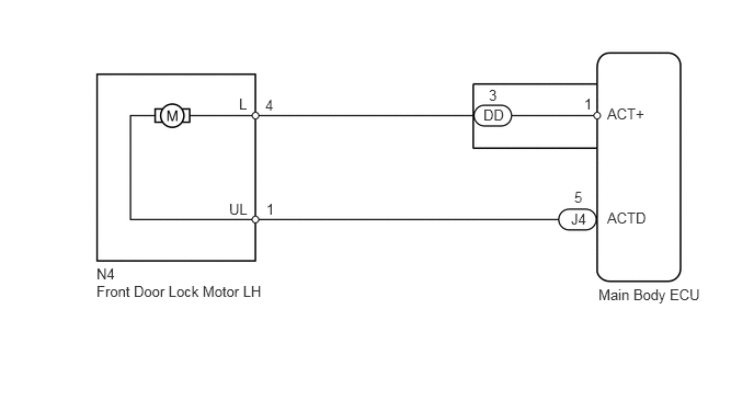
The main body ECU controls the front door lock motor LH to lock/unlock the front door LH. This ECU applies current from terminal ACT+ to terminal ACTD to operate the motor to lock the door. It reverses the direction of the current flow to operate the motor to unlock the door.

WIRING DIAGRAM
U152707E02
5.771,1 6.188,1.156 0.417,0.156 10 false ACT+ 5.771,1.99 6.177,2.146 0.406,0.156 10 false ACTD 5.688,2.719 6.719,2.875 1.031,0.156 10 false Main Body ECU 2.271,0.906 2.385,1.073 0.115,0.167 10 false L 2.177,1.906 2.375,2.083 0.198,0.177 10 false UL 2.521,0.917 2.677,1.094 0.156,0.177 10 false 4 2.531,1.906 2.688,2.083 0.156,0.177 10 false 1 4.594,1.01 4.813,1.188 0.219,0.177 10 false DD 4.646,0.823 4.802,1 0.156,0.177 10 false 3 5.427,2 5.594,2.177 0.167,0.177 10 false J4 5.458,1.792 5.615,1.969 0.156,0.177 10 false 5 0.917,2.688 2.573,3.021 1.656,0.333 10 false Front Door Lock Motor LH 5.552,0.906 5.708,1.083 0.156,0.177 10 false 1 0.917,2.521 1.115,2.698 0.198,0.177 10 false N4

PROCEDURE

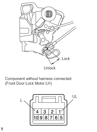
1.INSPECT FRONT DOOR LOCK MOTOR ASSEMBLY LH
E344848E01
2.177,3.938 2.594,3.521 false 1.25,3.927 0.844,3.563 false 2.188,1.99 2.802,2.188 0.615,0.198 10 false Lock 1.552,2.323 2.167,2.521 0.615,0.198 10 false Unlock 0.177,2.698 2.604,3.063 2.427,0.365 10 false Component without harness connected: (Front Door Lock Motor LH) 2.563,3.333 2.917,3.521 0.354,0.188 10 false UL 0.719,3.469 1.333,3.667 0.615,0.198 10 false L


b.

Apply battery voltage and check operation of the door lock motor.

OK:
Measurement Condition Specified Condition
Battery positive (+) → Terminal 4 (L)
Battery negative (-) → Terminal 1 (UL)
Lock
Battery positive (+) → Terminal 1 (UL)
Battery negative (-) → Terminal 4 (L)
Unlock


Result
Result Proceed to
OK A
NG (for Double Cab) B
NG (for Regular Cab) C
NG (for CrewMax) D


A

2.CHECK HARNESS AND CONNECTOR (FRONT DOOR LOCK MOTOR LH - MAIN BODY ECU)

B

REPLACE FRONT DOOR LOCK MOTOR ASSEMBLY LH

C

REPLACE FRONT DOOR LOCK MOTOR ASSEMBLY LH

D

REPLACE FRONT DOOR LOCK MOTOR ASSEMBLY LH

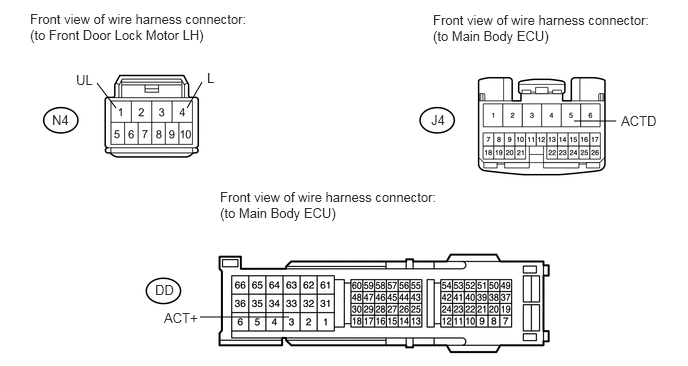
2.CHECK HARNESS AND CONNECTOR (FRONT DOOR LOCK MOTOR LH - MAIN BODY ECU)
U152801E02
1.208,1.125 1.01,0.865 false 1.948,1.125 2.104,0.854 false 3.01,3.302 2.083,3.302 false 5.979,1.26 6.417,1.26 false 0.313,0.115 2.688,0.5 2.375,0.385 10 false Front view of wire harness connector: (to Front Door Lock Motor LH) 0.792,0.75 1,0.927 0.208,0.177 10 false UL 0.542,1.167 0.75,1.344 0.208,0.177 10 false N4 1.615,2.938 1.865,3.115 0.25,0.177 10 false DD 1.708,3.229 2.115,3.406 0.406,0.177 10 false ACT+ 6.469,1.177 6.875,1.354 0.406,0.177 10 false ACTD 4.49,1.167 4.74,1.344 0.25,0.177 10 false J4 2.156,0.729 2.281,0.906 0.125,0.177 10 false L 2.292,1.969 4.646,2.333 2.354,0.365 10 false Front view of wire harness connector: (to Main Body ECU) 4.51,0.125 6.865,0.458 2.354,0.333 10 false Front view of wire harness connector: (to Main Body ECU)

a.

Disconnect the N4 door lock connector.


b.

Disconnect the DD and J4 ECU connectors.


c.

Measure the resistance according to the value(s) in the table below.

Standard resistance:
Tester Connection Condition Specified Condition
N4-4 (L) - DD-3 (ACT+) Always Below 1 Ω
N4-1 (UL) - J4-5 (ACTD)
DD-3 (ACT+) - Body ground Always 10 kΩ or higher
J4-5 (ACTD) - Body ground


OK

REPLACE MAIN BODY ECU

NG

REPAIR OR REPLACE HARNESS OR CONNECTOR