DOOR LOCK POWER DOOR LOCK CONTROL SYSTEM Door Control Switch Circuit
DESCRIPTION
When the lock side of the door control switch is pressed, continuity is established between terminal 1 (for regular cab) or 2 (except regular cab) and terminal 7 (for regular cab) or 1 (except regular cab) of the switch. When the unlock side of the switch is pressed, continuity is established between terminal 9 and terminal 7 (for regular cab) or 1 (except regular cab). Terminals L1 and UL1 of the main body ECU are connected to the door control switch, and door lock/unlock request signals (by door control switch operation) are input to the ECU. The main body ECU constantly applies voltage to terminal 1 (for regular cab) or 2 (except regular cab) of the door control switch via terminal L1. When the door control switch is operated to lock all doors, current flows from terminal L1 to terminal 1 (for regular cab) or 2 (except regular cab). The main body ECU determines that this is a door lock request signal input. The main body ECU also applies constant voltage to terminal 9 of the door control switch via terminal UL1. When the door control switch is operated to unlock the doors, current flows from terminal UL1 to terminal 9. The main body ECU determines that this is a door unlock request signal input.
When the lock side of the door control switch is pressed, continuity is established between terminal 4 and terminal 3 of the switch. When the unlock side of the switch is pressed, continuity is established between terminal 2 and terminal 3. Terminals L1 and UL1 of the main body ECU are connected to the door control switch, and door lock/unlock request signals (by door control switch operation) are input to the ECU. The main body ECU constantly applies voltage to terminal 4 of the door control switch via terminal L1. When the door control switch is operated to lock all doors, current flows from terminal L1 to terminal 4. The main body ECU determines that this is a door lock request signal input. The main body ECU also applies constant voltage to terminal 2 of the door control switch via terminal UL1. When the door control switch is operated to unlock the doors, current flows from terminal UL1 to terminal 2. The main body ECU determines that this is a door unlock request signal input.
WIRING DIAGRAM
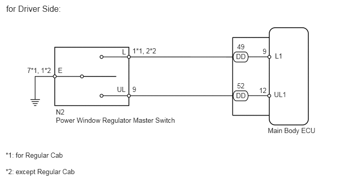
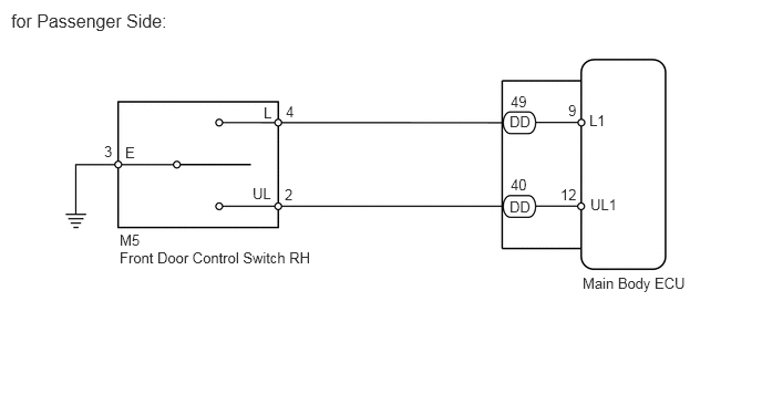
PROCEDURE
Check the Data List to ensure proper functioning of the door control switch.
| Tester Display | Measurement item/Range | Normal Condition | Diagnostic Note |
|---|---|---|---|
| Door Lock SW-Lock | Door control switch lock signal
/ ON or OFF |
ON: Door control switch is pushed to lock position
OFF: Door control switch is not pushed |
- |
| Door Lock SW-Unlock | Door control switch unlock signal
/ ON or OFF |
ON: Door control switch is pushed to unlock position
OFF: Door control switch is not pushed |
- |
- OK:
The display is as specified in the normal condition column.
| Result | Proceed to |
|---|---|
| OK | A |
| NG (for Driver Side) | B |
| NG (for Passenger Side) | C |
A
B
C
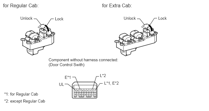
Remove the master switch (see page Vehicle Interior>DOOR LOCK>DOOR CONTROL SWITCH(for Front LH)>REMOVAL).
Measure the resistance according to the value(s) in the table below.
- Standard resistance:
- for Regular Cab:
Tester Connection Switch Condition Specified Condition 1 (L) - 7 (E) Lock Below 1 Ω 1 (L) - 7 (E) OFF (Free) 10 kΩ or higher 9 (UL) - 7 (E) 9 (UL) - 7 (E) Unlock Below 1 Ω
- except Regular Cab:
Tester Connection Switch Condition Specified Condition 2 (L) - 1 (E) Lock Below 1 Ω 2 (L) - 1 (E) OFF (Free) 10 kΩ or higher 9 (UL) - 1 (E) 9 (UL) - 1 (E) Unlock Below 1 Ω
OK
NG
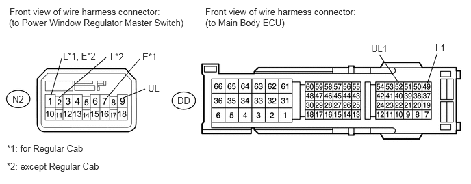
Disconnect the N2 switch connector.
Disconnect the DD ECU connector.
Measure the resistance according to the value(s) in the table below.
- Standard resistance:
- for Regular Cab:
Tester Connection Condition Specified Condition N2-1 (L) - DD-49 (L1) Always Below 1 Ω N2-9 (UL) - DD-52 (UL1) N2-7 (E) - Body ground DD-49 (L1) - Body ground Always 10 kΩ or higher DD-52 (UL1) - Body ground
- except Regular Cab:
Tester Connection Condition Specified Condition N2-2 (L) - DD-49 (L1) Always Below 1 Ω N2-9 (UL) - DD-52 (UL1) N2-1 (E) - Body ground DD-49 (L1) - Body ground Always 10 kΩ or higher DD-52 (UL1) - Body ground
OK
NG
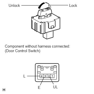
Remove the door control switch (see page Vehicle Interior>DOOR LOCK>DOOR CONTROL SWITCH(for Front RH)>REMOVAL ).
Measure the resistance according to the value(s) in the table below.
- Standard resistance:
Tester Connection Switch Condition Specified Condition 4 (L) - 3 (E) Lock Below 1 Ω 4 (L) - 3 (E) OFF 10 kΩ or higher 2 (UL) - 3 (E) 2 (UL) - 3 (E) Unlock Below 1 Ω
OK
NG
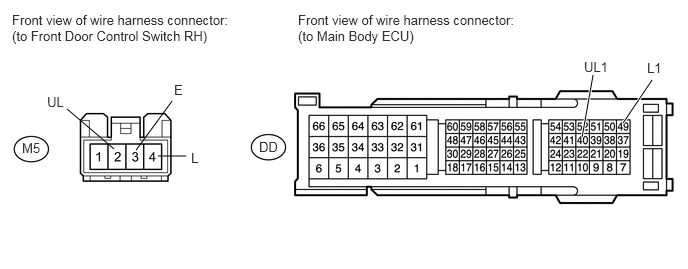
Disconnect the M5 switch connector.
Disconnect the DD ECU connector.
Measure the resistance according to the value(s) in the table below.
- Standard resistance:
Tester Connection Condition Specified Condition M5-4 (L) - DD-49 (L1) Always Below 1 Ω M5-2 (UL) - DD-40 (UL1) M5-3 (E) - Body ground DD-49 (L1) - Body ground Always 10 kΩ or higher DD-40 (UL1) - Body ground
OK
NG