DOOR LOCK POWER DOOR LOCK CONTROL SYSTEM Driver Side Door Key Lock and Unlock Switch Circuit
DESCRIPTION
The Front door key lock and unlock switch LH is built into the Front door lock motor LH. When the Front door key cylinder LH is turned to lock all the doors using the key, there is continuity between terminals L and E of the key lock and unlock switch. When the cylinder is turned to unlock the doors, there is continuity between terminals UL and E. Terminals L2 and UL3 of the main body ECU are connected to the door lock motor, and door lock/unlock request signals (by key) are input to the main body ECU. The main body ECU constantly applies voltage to terminal L of the front door lock motor LH via terminal L2. When the front door key cylinder LH is turned to lock all the doors using the key, current flows from terminal L2 to terminal L. The main body ECU also applies constant voltage to terminal UL of the door lock motor via terminal UL3. When the door key cylinder is turned to unlock the doors using the key, current flows from terminal UL3 to terminal UL.
WIRING DIAGRAM
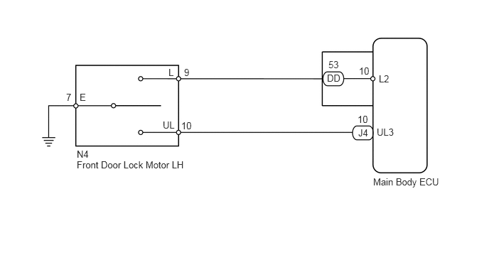
PROCEDURE
Check the Data List to ensure proper functioning of the door key lock and unlock switch.
| Tester Display | Measurement item/Range | Normal Condition | Diagnostic Note |
|---|---|---|---|
| Door Key SW-Lock | Driver door lock/unlock switch lock signal (Key-linked lock switch) / ON or OFF | ON: Driver side door key cylinder is turned to lock position
OFF: Driver side door key cylinder is not turned |
- |
| Door Key SW-Unlock | Driver door lock/unlock switch unlock signal (Key-linked unlock switch) / ON or OFF | ON: Driver side door key cylinder is turned to unlock position
OFF: Driver side door key cylinder is not turned |
- |
| D Door Key SW-UL | Driver door lock/unlock switch unlock signal (2 step key-linked unlock switch) / ON or OFF | ON: Driver side door key cylinder is turned to unlock position
OFF: Driver side door key cylinder is not turned |
- |
- OK:
The display is as specified in the normal condition column.
OK
NG
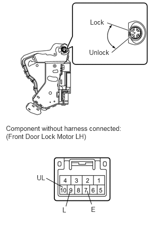
Remove the front door lock motor LH.
for Double Cab: (See page Vehicle Interior>DOOR LOCK>FRONT DOOR LOCK(for Double Cab)>REMOVAL)
for Regular Cab: (See page Vehicle Interior>DOOR LOCK>FRONT DOOR LOCK(for Regular Cab)>REMOVAL)
for CrewMax: (See page Vehicle Interior>DOOR LOCK>FRONT DOOR LOCK(for CrewMax)>REMOVAL)
Measure the resistance according to the value(s) in the table below.
- Standard resistance:
Tester Connection Switch Condition Specified Condition 7 (E) - 9 (L) ON (Door lock set to LOCK) Below 1 Ω 7 (E) - 9 (L)
7 (E) - 10 (UL)OFF (Free) 10 kΩ or higher 7 (E) - 10 (UL) ON (Door lock set to UNLOCK) Below 1 Ω
| Result | Proceed to |
|---|---|
| OK | A |
| NG (for Double Cab) | B |
| NG (for Regular Cab) | C |
| NG (for CrewMax) | D |
A
B
C
D
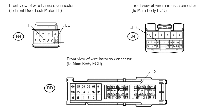
Disconnect the N4 door lock connector.
Disconnect the DD and J4 ECU connectors.
Measure the resistance according to the value(s) in the table below.
- Standard resistance:
Tester Connection Condition Specified Condition N4-9 (L) - DD-53 (L2) Always Below 1 Ω N4-10 (UL) - J4-10 (UL3) N4-7 (E) - Body ground N4-10 (UL) - Body ground Always 10 kΩ or higher N4-9 (L) - Body ground
OK
NG