Home › Vehicle Interior › AIR CONDITIONING › AIR CONDITIONING SYSTEM(for Manual Air Conditioning System)
RM27M0U _58 Vehicle Interior _049154 AIR CONDITIONING _0234411 AIR CONDITIONING SYSTEM(for Manual Air Conditioning System) D

AIR CONDITIONING  AIR CONDITIONING SYSTEM(for Manual Air Conditioning System)  SYSTEM DESCRIPTION  


GENERAL


a.

The air conditioning system has the following controls:

Control Outline
Manual Control The air conditioning amplifier controls the damper positions (air inlet control damper, air mix control damper and mode control damper) and blower speed in accordance with the positions of the switches (temperature control switch, blower switch, mode select switch and air inlet control switch).
MAX A/C Control When the temperature control switch is in the MAX A/C position, the air conditioning amplifier turns the compressor on and activates the servo motor (air inlet) to set the air inlet control damper to the RECIRC position, improving the cooling efficiency.
Compressor Control Through the calculation of the target evaporator temperature based on various sensor signals, the air conditioning amplifier optimally controls the discharge capacity by regulating the opening extent of the air conditioning compressor solenoid valve.
The air conditioning amplifier compares the pulley speed signals, which are transmitted by the lock sensor located on the air conditioning compressor, with the engine speed signals, which are transmitted by the ECM (crankshaft position sensor). When the air conditioning amplifier determines that the pulley is locked, it turns off the magnetic clutch.
Self-Diagnosis A DTC (Diagnostic Trouble Code) is stored in the memory when the air conditioning amplifier detects a problem with the air conditioning system.


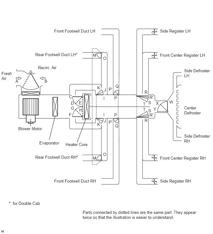
MODE POSITION AND DAMPER OPERATION (for Regular Cab and Double Cab)


a.

Mode Position and Damper Operation

E147783E02
1.854,3.896 1.656,4.698 false 1.031,4.24 1.031,3.99 false 2.896,3.969 2.594,4.781 false 0.521,2.646 0.635,2.792 0.115,0.146 10 false A 1.5,2.646 1.615,2.792 0.115,0.146 10 false B 2.323,3.771 2.438,3.917 0.115,0.146 10 false F 2.385,3.552 2.51,3.698 0.125,0.146 10 false G 2.667,3.615 2.781,3.76 0.115,0.146 10 false H 3.479,3.771 3.594,3.917 0.115,0.146 10 false I 3.479,3.219 3.594,3.365 0.115,0.146 10 false I 3.5,3.979 3.615,4.125 0.115,0.146 10 false J 3.5,2.938 3.615,3.083 0.115,0.146 10 false J 3.271,4.094 3.385,4.24 0.115,0.146 10 false K 3.271,2.865 3.385,3.01 0.115,0.146 10 false K 0.052,2.385 0.448,2.698 0.396,0.313 10 false Fresh Air 0.615,4.24 1.448,4.448 0.833,0.208 10 false Blower Motor 1.323,4.719 2.042,4.917 0.719,0.198 10 false Evaporator 2.208,4.771 2.979,4.958 0.771,0.188 10 false Heater Core 1.281,2.188 1.969,2.375 0.688,0.188 10 false Recirc. Air 5.385,5.229 6.969,5.438 1.583,0.208 10 false Front Center Register RH 5.385,1.771 6.969,1.948 1.583,0.177 10 false Front Center Register LH 5.385,6 6.49,6.198 1.104,0.198 10 false Side Register RH 5.385,0.958 6.5,1.156 1.115,0.198 10 false Side Register LH 1.823,6 3.313,6.208 1.49,0.208 10 false Front Footwell Duct RH 1.823,0.958 3.281,1.146 1.458,0.188 10 false Front Footwell Duct LH 1.188,5.198 2.708,5.375 1.521,0.177 10 false Rear Footwell Duct RH* 0.302,6.75 1.448,6.958 1.146,0.208 10 false *: for Double Cab 1.188,1.75 2.729,1.969 1.542,0.219 10 false Rear Footwell Duct LH* 6.198,4.49 7.083,4.844 0.885,0.354 10 false Side Defroster RH 6.198,2.292 7.104,2.646 0.906,0.354 10 false Side Defroster LH 6.198,3.542 6.781,3.917 0.583,0.375 10 false Center Defroster 3.844,3.208 3.958,3.354 0.115,0.146 10 false P 3.844,3.781 3.958,3.927 0.115,0.146 10 false P 3.656,2.917 3.813,3.063 0.156,0.146 10 false P' 3.656,4.021 3.813,4.167 0.156,0.146 10 false P' 3.885,2.813 4.01,2.958 0.125,0.146 10 false Q 3.469,1.875 3.594,2.021 0.125,0.146 10 false O 3.125,1.771 3.26,1.917 0.135,0.146 10 false M 3.469,5.104 3.594,5.25 0.125,0.146 10 false O 3.125,5.229 3.26,5.375 0.135,0.146 10 false M 3.875,4.146 4,4.292 0.125,0.146 10 false Q 4.865,3.01 4.979,3.156 0.115,0.146 10 false R 4.865,3.958 4.979,4.104 0.115,0.146 10 false R 5.031,3.188 5.208,3.333 0.177,0.146 10 false R' 5.031,3.781 5.208,3.927 0.177,0.146 10 false R' 4.99,3.365 5.104,3.51 0.115,0.146 10 false S 5.25,3.385 5.365,3.531 0.115,0.146 10 false X 5.167,3.583 5.281,3.729 0.115,0.146 10 false Y 4.99,3.635 5.104,3.781 0.115,0.146 10 false S 4.813,3.417 4.927,3.563 0.115,0.146 10 false T 4.813,3.604 4.927,3.75 0.115,0.146 10 false T 5.698,3.344 5.844,3.49 0.146,0.146 10 false W 2.323,3.167 2.438,3.313 0.115,0.146 10 false C 2.385,3.385 2.5,3.531 0.115,0.146 10 false D 2.656,3.375 2.771,3.521 0.115,0.146 10 false E 2.781,7.052 6.698,7.438 3.917,0.385 10 false Parts connected by dotted lines are the same part. They appear twice so that the illustration is easier to understand.

Functions of Main Dampers:
Control Damper Operation Position Damper Position Operation
Air Inlet Control Damper FRESH B Brings in fresh air.
RECIRC A Recirculates internal air.
Air Mix Control Damper MAX COLD to MAX HOT Temperature Setting C - E
F - H
I - K
Varies the mixture ratio of fresh air and recirculated air in order to regulate the temperature continuously from HOT to COLD.
Air Outlet Control Damper FACE
E264852

O, P, T, W Air blows out of the front center register, side registers, and footwell ducts.*1
BI-LEVEL
E264849

M, P', S, W Air mainly blows out of the front center register, side register, and footwell ducts.
FOOT
E264850

M, Q, R', X Air mainly blows out of the front and rear footwell ducts. In addition, air blows out slightly from the front and side defrosters, front center register, and side register.*2
FOOT / DEF
E264851

M, P', R', Y' Air mainly blows out of the front and side defrosters to defrost the windshield; air also blows out from the front and rear footwell ducts, front center register, and side register.*2
DEF
E264847

O, P, R, Y Air blows out of the front and side defrosters and side registers to defrost the windshield.

HINT:

*1: In multi mode, air blows out of all the air outlets except the front and side defrosters.

*2: In multi mode, air blows out of all the air outlets.


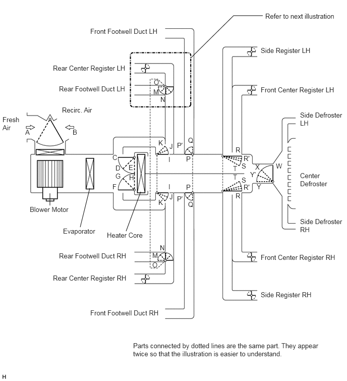
MODE POSITION AND DAMPER OPERATION (for CrewMax)


a.

Mode Position and Damper Operation

E148812E02
1.854,3.885 1.656,4.688 false 1.031,4.24 1.031,3.99 false 2.906,3.958 2.604,4.771 false 3.948,1.188 4.823,0.323 4.823,0.323 5.427,0.323 false 0.521,2.646 0.635,2.792 0.115,0.146 10 false A 1.5,2.646 1.615,2.792 0.115,0.146 10 false B 2.323,3.771 2.438,3.917 0.115,0.146 10 false F 2.385,3.552 2.51,3.698 0.125,0.146 10 false G 2.667,3.583 2.781,3.729 0.115,0.146 10 false H 3.479,3.771 3.594,3.917 0.115,0.146 10 false I 3.479,3.208 3.594,3.354 0.115,0.146 10 false I 3.5,3.979 3.615,4.125 0.115,0.146 10 false J 3.5,2.938 3.615,3.083 0.115,0.146 10 false J 3.271,4.094 3.385,4.24 0.115,0.146 10 false K 3.271,2.865 3.385,3.01 0.115,0.146 10 false K 3.177,1.615 3.302,1.76 0.125,0.146 10 false O 3.167,1.813 3.302,1.958 0.135,0.146 10 false M 3.313,1.969 3.438,2.115 0.125,0.146 10 false N 3.146,5.385 3.271,5.531 0.125,0.146 10 false O 3.146,5.188 3.281,5.333 0.135,0.146 10 false M 3.302,5.031 3.427,5.177 0.125,0.146 10 false N 0.052,2.385 0.427,2.719 0.375,0.333 10 false Fresh Air 0.615,4.24 1.448,4.427 0.833,0.188 10 false Blower Motor 1.302,4.688 2,4.865 0.698,0.177 10 false Evaporator 2.208,4.771 2.979,4.958 0.771,0.188 10 false Heater Core 1.281,2.188 1.969,2.375 0.688,0.188 10 false Recirc. Air 5.385,5.229 6.979,5.417 1.594,0.188 10 false Front Center Register RH 5.385,1.771 7,1.979 1.615,0.208 10 false Front Center Register LH 5.385,6 6.479,6.188 1.094,0.188 10 false Side Register RH 5.385,0.958 6.5,1.167 1.115,0.208 10 false Side Register LH 1.865,6.375 3.313,6.573 1.448,0.198 10 false Front Footwell Duct RH 1.865,0.563 3.313,0.781 1.448,0.219 10 false Front Footwell Duct LH 1.219,5.198 2.656,5.417 1.438,0.219 10 false Rear Footwell Duct RH 1.094,5.656 2.635,5.854 1.542,0.198 10 false Rear Center Register RH 1.094,1.323 2.615,1.51 1.521,0.188 10 false Rear Center Register LH 1.219,1.75 2.615,1.958 1.396,0.208 10 false Rear Footwell Duct LH 6.198,4.49 7.094,4.833 0.896,0.344 10 false Side Defroster RH 6.198,2.292 7.083,2.635 0.885,0.344 10 false Side Defroster LH 6.198,3.542 6.813,3.906 0.615,0.365 10 false Center Defroster 3.844,3.198 3.958,3.344 0.115,0.146 10 false P 3.844,3.781 3.958,3.927 0.115,0.146 10 false P 3.656,2.917 3.813,3.063 0.156,0.146 10 false P' 3.656,4.021 3.813,4.167 0.156,0.146 10 false P' 3.885,2.813 4.01,2.958 0.125,0.146 10 false Q 3.885,4.135 4.01,4.281 0.125,0.146 10 false Q 4.865,3.01 4.979,3.156 0.115,0.146 10 false R 4.865,3.958 4.979,4.104 0.115,0.146 10 false R 5.031,3.188 5.208,3.333 0.177,0.146 10 false R' 5.167,3.521 5.323,3.667 0.156,0.146 10 false Y' 5.031,3.781 5.208,3.927 0.177,0.146 10 false R' 4.99,3.344 5.104,3.49 0.115,0.146 10 false S 5.271,3.365 5.385,3.51 0.115,0.146 10 false X 5.302,3.771 5.417,3.917 0.115,0.146 10 false Y 4.99,3.635 5.104,3.781 0.115,0.146 10 false S 4.813,3.396 4.927,3.542 0.115,0.146 10 false T 4.813,3.573 4.927,3.719 0.115,0.146 10 false T 5.698,3.344 5.844,3.49 0.146,0.146 10 false W 2.323,3.167 2.438,3.313 0.115,0.146 10 false C 2.385,3.385 2.5,3.531 0.115,0.146 10 false D 2.656,3.375 2.771,3.521 0.115,0.146 10 false E 2.75,7.052 6.635,7.406 3.885,0.354 10 false Parts connected by dotted lines are the same part. They appear twice so that the illustration is easier to understand. 5.479,0.25 6.979,0.469 1.5,0.219 10 false Refer to next illustration

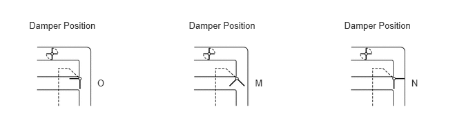
E151139E01
0.439,0.299 1.493,0.462 1.054,0.162 10 Damper Position 1.467,1.177 1.622,1.340 0.156,0.162 10 O 3.848,1.177 4.004,1.340 0.156,0.162 10 M 6.207,1.177 6.362,1.340 0.156,0.162 10 N 2.849,0.299 3.903,0.462 1.054,0.162 10 Damper Position 5.193,0.299 6.247,0.462 1.054,0.162 10 Damper Position

Functions of Main Dampers:
Control Damper Operation Position Damper Position Operation
Air Inlet Control Damper FRESH B Brings in fresh air.
RECIRC A Recirculates internal air.
Air Mix Control Damper MAX COLD to MAX HOT Temperature Setting C - E
F - H
I - K
Varies the mixture ratio of fresh air and recirculated air in order to regulate the temperature continuously from HOT to COLD.
Air Outlet Control Damper FACE
E264852

O, P, T, W Air blows out of the front center register, side registers, and footwell ducts.*1
BI-LEVEL
E264849

M, P', S, W Air mainly blows out of the front center register, side register, and footwell ducts.
FOOT
E264850

M, Q, R', X Air mainly blows out of the front and rear footwell ducts. In addition, air blows out slightly from the front and side defrosters, front center register, and side register.*2
FOOT / DEF
E264851

M, P', R', Y' Air mainly blows out of the front and side defrosters to defrost the windshield; air also blows out from the front and rear footwell ducts, front center register, and side register.*2
DEF
E264847

N, P, R, Y Air blows out of the front and side defrosters and side registers to defrost the windshield.

HINT:

*1: In multi mode, air blows out of all the air outlets except the front and side defrosters.

*2: In multi mode, air blows out of all the air outlets.


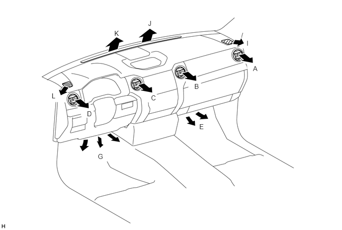
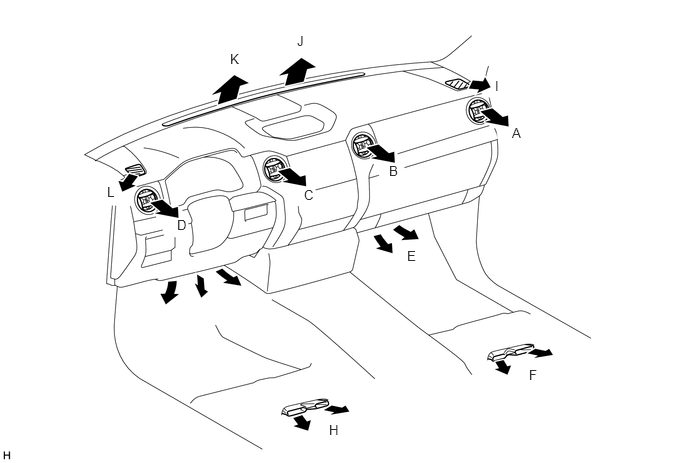
AIR OUTLETS AND AIRFLOW VOLUME (for Regular Cab)


a.

Air Outlets and Airflow Volume

E275650E02
5.302,1.354 5.479,1.51 0.177,0.156 10 false A 4.073,1.729 4.188,1.865 0.115,0.135 10 false B 3.167,1.969 3.333,2.156 0.167,0.188 10 false C 1.823,2.302 1.979,2.469 0.156,0.167 10 false D 4.177,2.573 4.354,2.75 0.177,0.177 10 false E 2.052,3.198 2.208,3.375 0.156,0.177 10 false G 5.167,0.823 5.292,0.979 0.125,0.156 10 false I 3.104,0.406 3.26,0.583 0.156,0.177 10 false J 2.396,0.615 2.552,0.792 0.156,0.177 10 false K 1.083,1.927 1.229,2.094 0.146,0.167 10 false L

INDICATION
(MODE)
FACE FOOT DEF
CENTER SIDE FRONT CENTER SIDE
Driver Side Passenger Side Driver Side Passenger Side Driver Side Passenger Side Driver Side Passenger Side Driver Side Passenger Side
C B D A G E K J L I
E264852

FACE
E344736

E344736

E344736

E344736

- - - - - -
Mid1
E344742

E344742

E344742

E344742

E344741

E344741

- - - -
E264849

B/L
E344739

E344739

E344739

E344739

E344740

E344740

- - - -
Mid2
E344845

E344845

E344845

E344845

E344739

E344739

- - - -
E264850

FOOT
E344741

E344741

E344741

E344741

E344737

E344737

E344741

E344741

E344738

E344738

Mid3
E344741

E344741

E344741

E344741

E344742

E344742

E344740

E344740

E344741

E344741

E264851

F/D
E344741

E344741

E344741

E344741

E344739

E344739

E344739

E344739

E344740

E344740

Mid4
E344741

E344741

E344741

E344741

E344740

E344740

E344742

E344742

E344845

E344845

E264847

DEF
- - - - - -
E344736

E344736

E344742

E344742


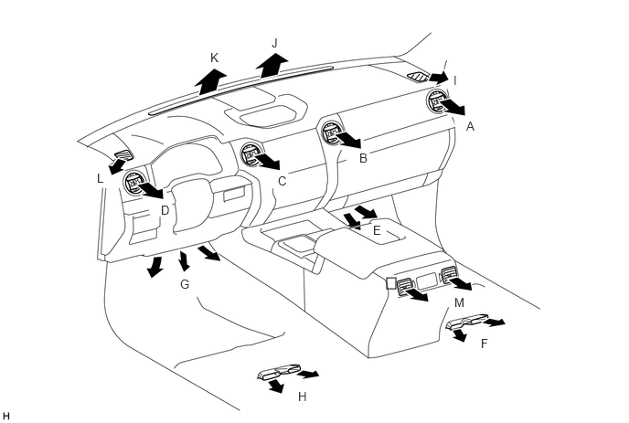
AIR OUTLETS AND AIRFLOW VOLUME (for Double Cab)


a.

Air Outlets and Airflow Volume

E275651E02
5.333,1.302 5.479,1.479 0.146,0.177 10 false A 4.052,1.698 4.198,1.865 0.146,0.167 10 false B 3.167,1.948 3.323,2.135 0.156,0.188 10 false C 1.844,2.26 2.01,2.458 0.167,0.198 10 false D 4.24,2.583 4.396,2.75 0.156,0.167 10 false E 3.427,4.396 3.625,4.583 0.198,0.188 10 false H 5.51,3.823 5.708,4.01 0.198,0.188 10 false F 5.156,0.813 5.271,0.99 0.115,0.177 10 false I 3.094,0.344 3.229,0.531 0.135,0.188 10 false J 2.396,0.531 2.542,0.708 0.146,0.177 10 false K 1.115,1.917 1.271,2.094 0.156,0.177 10 false L

INDICATION
(MODE)
FACE FOOT DEF
CENTER SIDE FRONT REAR CENTER SIDE
Driver Side Passenger Side Driver Side Passenger Side Driver Side Passenger Side Driver Side Passenger Side Driver Side Passenger Side Driver Side Passenger Side
C B D A G E H F K J L I
E264852

FACE
E344736

E344736

E344736

E344736

- - - - - - - -
Mid1
E344742

E344742

E344742

E344742

E344741

E344741

E344741

E344741

- - - -
E264849

B/L
E344739

E344739

E344739

E344739

E344740

E344740

E344740

E344740

- - - -
Mid2
E344845

E344845

E344845

E344845

E344739

E344739

E344739

E344739

- - - -
E264850

FOOT
E344741

E344741

E344741

E344741

E344737

E344737

E344739

E344739

E344741

E344741

E344738

E344738

Mid3
E344741

E344741

E344741

E344741

E344742

E344742

E344845

E344845

E344740

E344740

E344741

E344741

E264851

F/D
E344741

E344741

E344741

E344741

E344739

E344739

E344740

E344740

E344739

E344739

E344740

E344740

Mid4
E344741

E344741

E344741

E344741

E344740

E344740

E344741

E344741

E344742

E344742

E344845

E344845

E264847

DEF
- - - - - - - -
E344736

E344736

E344742

E344742


AIR OUTLETS AND AIRFLOW VOLUME (for CrewMax)


a.

Air Outlets and Airflow Volume

E275652E02
4.406,3.167 4.51,3.292 0.104,0.125 5.313,1.354 5.479,1.521 0.167,0.167 10 false A 4.094,1.719 4.24,1.896 0.146,0.177 10 false B 3.167,1.979 3.333,2.156 0.167,0.177 10 false C 1.833,2.313 2,2.5 0.167,0.188 10 false D 4.25,2.542 4.365,2.677 0.115,0.135 10 false E 5.479,3.833 5.646,4.01 0.167,0.177 10 false F 5.177,3.365 5.385,3.542 0.208,0.177 10 false M 3.396,4.438 3.563,4.615 0.167,0.177 10 false H 2.052,3.156 2.219,3.333 0.167,0.177 10 false G 5.167,0.833 5.313,1.01 0.146,0.177 10 false I 2.396,0.573 2.552,0.76 0.156,0.188 10 false K 1.104,1.948 1.271,2.146 0.167,0.198 10 false L 3.094,0.406 3.25,0.594 0.156,0.188 10 false J

INDICATION
(MODE)
FACE FOOT DEF
CENTER SIDE REAR FRONT REAR CENTER SIDE
Driver Side Passenger Side Driver Side Passenger Side - Driver Side Passenger Side Driver Side Passenger Side Driver Side Passenger Side Driver Side Passenger Side
C B D A M G E H F K J L I
E264852

FACE
E344736

E344736

E344736

E344736

E344736

- - - - - - - -
Mid1
E344742

E344742

E344742

E344742

E344742

E344741

E344741

E344741

E344741

- - - -
E264849

B/L
E344739

E344739

E344739

E344739

E344739

E344740

E344740

E344740

E344740

- - - -
Mid2
E344845

E344845

E344845

E344845

E344739

E344739

E344739

E344739

E344739

- - - -
E264850

FOOT
E344741

E344741

E344741

E344741

E344739

E344737

E344737

E344739

E344739

E344741

E344741

E344738

E344738

Mid3
E344741

E344741

E344741

E344741

E344739

E344742

E344742

E344845

E344845

E344740

E344740

E344741

E344741

E264851

F/D
E344741

E344741

E344741

E344741

E344739

E344739

E344739

E344740

E344740

E344739

E344739

E344740

E344740

Mid4
E344741

E344741

E344741

E344741

E344739

E344740

E344740

E344741

E344741

E344742

E344742

E344845

E344845

E264847

DEF
- - - - - - - - -
E344736

E344736

E344742

E344742