RM27M0U
_58
Vehicle Interior
_049155
THEFT DETERRENT
_0234426
THEFT DETERRENT SYSTEM
J
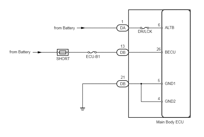
THEFT DETERRENT THEFT DETERRENT SYSTEM ECU Power Source Circuit
DESCRIPTION
This circuit provides power to operate the main body ECU.
WIRING DIAGRAM
5.792,0.885 6.156,1.063
0.365,0.177
10
false
ALTB
5.552,0.792 5.708,0.969
0.156,0.177
10
false
6
4.844,1.021 5.365,1.198
0.521,0.177
10
false
DR/LCK
4.219,0.896 4.427,1.073
0.208,0.177
10
false
DA
4.26,0.677 4.417,0.854
0.156,0.177
10
false
1
5.792,1.75 6.198,1.927
0.406,0.177
10
false
BECU
5.5,1.646 5.667,1.823
0.167,0.177
10
false
26
5.792,2.854 6.198,3.031
0.406,0.177
10
false
GND1
5.792,3.479 6.198,3.656
0.406,0.177
10
false
GND2
5.542,2.75 5.698,2.927
0.156,0.177
10
false
5
5.542,3.385 5.698,3.563
0.156,0.177
10
false
4
5.49,4.208 6.49,4.385
1,0.177
10
false
Main Body ECU
4.219,2.865 4.438,3.042
0.219,0.177
10
false
DB
4.24,2.635 4.406,2.813
0.167,0.177
10
false
21
4.219,1.76 4.427,1.938
0.208,0.177
10
false
DB
4.229,1.542 4.396,1.719
0.167,0.177
10
false
13
3.021,1.906 3.542,2.083
0.521,0.177
10
false
ECU-B1
1.979,1.979 2.479,2.156
0.5,0.177
10
false
SHORT
1.896,0.896 2.667,1.073
0.771,0.177
10
false
from Battery
0.333,1.74 1.104,1.917
0.771,0.177
10
false
from Battery
PROCEDURE
1.INSPECT FUSE (DR/LCK, ECU-B1)
a.
Remove the DR/LCK fuse from the main body ECU.
b.
Remove the ECU-B1 fuse from the engine room junction block unit B.
c.
Measure the resistance according to the value(s) in the table below.
- Standard resistance:
Tester Connection Condition Specified Condition DR/LCK fuse Always Below 1 Ω ECU-B1 fuse
OK
2.CHECK HARNESS AND CONNECTOR (MAIN BODY ECU - BATTERY AND BODY GROUND)
NG
REPLACE FUSE
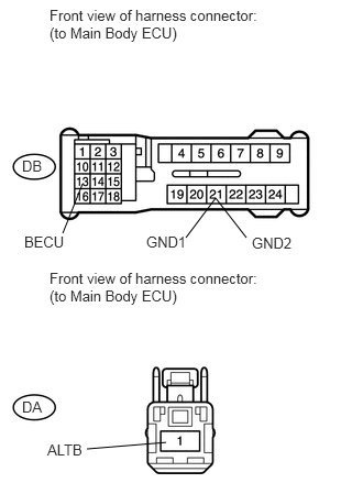
2.CHECK HARNESS AND CONNECTOR (MAIN BODY ECU - BATTERY AND BODY GROUND)
a.
1.573,4.188 0.823,4.25
false
0.781,1.74 0.594,2.208
false
2.042,1.875 2.333,2.25
false
2.042,1.875 1.76,2.25
false
0.469,0.063 2.573,0.458
2.104,0.396
10
false
Front view of harness connector: (to Main Body ECU)
0.469,2.552 2.573,2.948
2.104,0.396
10
false
Front view of harness connector: (to Main Body ECU)
0.448,4.177 0.865,4.365
0.417,0.188
10
false
ALTB
0.229,2.208 0.646,2.396
0.417,0.188
10
false
BECU
0.208,1.49 0.625,1.677
0.417,0.188
10
false
DB
1.385,2.208 1.802,2.396
0.417,0.188
10
false
GND1
2.385,2.219 2.823,2.406
0.438,0.188
10
false
GND2
0.208,3.771 0.625,3.958
0.417,0.188
10
false
DA
Disconnect the DA and DB main body ECU connectors.
b.
Measure the voltage according to the value(s) in the table below.
- Standard voltage:
Tester Connection Condition Specified Condition DB-13 (BECU) - Body ground Always 11 to 14 V DA-1 (ALTB) - Body ground
c.
Measure the resistance according to the value(s) in the table below.
- Standard resistance:
Tester Connection Condition Specified Condition DB-21 (GND1, GND2) - Body ground Always Below 1 Ω
OK
PROCEED TO NEXT CIRCUIT INSPECTION SHOWN IN PROBLEM SYMPTOMS TABLE
NG
REPAIR OR REPLACE HARNESS OR CONNECTOR