RM27M0U
_58
Vehicle Interior
_049155
THEFT DETERRENT
_0234426
THEFT DETERRENT SYSTEM
J
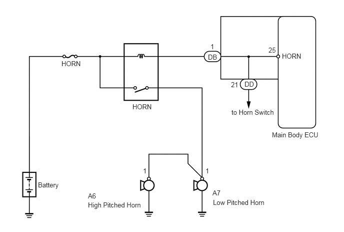
THEFT DETERRENT THEFT DETERRENT SYSTEM Horn Circuit
DESCRIPTION
When the theft deterrent system changes from the armed state to the alarm sounding state, the main body ECU transmits a signal to cause the horns to sound at 0.4 second intervals.
WIRING DIAGRAM
0.792,3.76 1.302,3.979
0.51,0.219
10
false
Battery
1.281,1.24 1.771,1.458
0.49,0.219
10
false
HORN
2.76,2.135 3.302,2.354
0.542,0.219
10
false
HORN
5.875,1.083 6.896,1.438
1.021,0.354
10
false
HORN
1.833,3.99 2.417,4.208
0.583,0.219
10
false
A6
4.385,0.885 4.969,1.104
0.583,0.219
10
false
1
5.594,0.958 6.177,1.177
0.583,0.219
10
false
25
4.813,1.677 5.396,1.896
0.583,0.219
10
false
21
4.281,3.469 4.521,3.708
0.24,0.24
10
false
1
2.979,3.469 3.156,3.688
0.177,0.219
10
false
1
4.427,3.927 5.01,4.146
0.583,0.219
10
false
A7
4.333,1.104 4.76,1.344
0.427,0.24
10
false
DB
5.094,1.667 5.521,1.906
0.427,0.24
10
false
DD
4.823,2.25 5.917,2.448
1.094,0.198
10
false
to Horn Switch
5.667,2.719 6.729,2.948
1.063,0.229
10
false
Main Body ECU
4.438,4.125 6.177,4.406
1.74,0.281
10
false
Low Pitched Horn
1.833,4.177 3.031,4.427
1.198,0.25
10
false
High Pitched Horn
PROCEDURE
1.CHECK HORN ASSEMBLY
a.
Press the horn switch and check if the vehicle horns sound normally.
- OK:
Vehicle horns sound normally.
OK
PROCEED TO NEXT CIRCUIT INSPECTION SHOWN IN PROBLEM SYMPTOMS TABLE
NG