METER / GAUGE / DISPLAY METER / GAUGE SYSTEM SYSTEM DESCRIPTION
METER GAUGE AND WARNING/INDICATOR
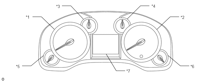
| *1 | Tachometer | *2 | Speedometer |
| *3 | Engine Coolant Temperature Receiver Gauge | *4 | Fuel Receiver Gauge |
| *5 | Oil Pressure Receiver Gauge | *6 | Voltmeter |
| *7 | Multi-information Display | - | - |
| Item | Details |
|---|---|
| Speedometer | Based on signal received from wheel speed sensor, skid control ECU calculates vehicle speed and transmits data to combination meter (CAN) |
| Tachometer | Combination meter receives engine speed signal from ECM, and gauge needle operates (CAN) |
| ODO/TRIP meter | ·
Combination meter receives vehicle speed pulse integration signal from skid control ECU, and ODO/TRIP meter display operates (CAN) ·
Using ODO/TRIP switch, ODO/TRIP meter display changes |
| Fuel receiver gauge | Combination meter receives fuel amount information measured by fuel sender gauge, and gauge needle operates (Direct line) |
| Engine coolant temperature gauge | Combination meter receives water temperature signal from ECM, and gauge needle operates (CAN) |
| Oil pressure receiver gauge | Combination meter receives engine speed signal from ECM (CAN), and receives oil pressure sender signal from oil pressure sender (Direct line). Then meter measures signals and gauge needle operates. |
| Voltmeter | Monitors IG voltage and gauge needle operates (Direct line) |
| Item | Details |
|---|---|
BEAM indicator light

|
Receives signal from main body ECU (CAN) |
SRS warning light

|
Receives malfunction signal from center airbag sensor (CAN) |
DOOR indicator light

|
Open door indicator comes on when signal is received from main body ECU (CAN) |
Front seat belt warning light

|
·
Receives driver seat belt signal (Unfastened) from main body ECU (CAN) ·
Receives front passenger seat belt signal (Unfastened) from center airbag sensor (CAN) |
Brake warning light*2

|
·
Comes on when parking brake switch is ON (CAN) ·
Brake fluid level warning switch is ON (Direct line) ·
Vehicle stability control system is malfunctioning |
Brake warning light*3

|
|
CHARGE warning light

|
Receives malfunction signal from generator (Direct line) |
4LO indicator light*1

|
Receives 4LO signal from 4WD control ECU (CAN) |
ABS warning light*2

|
Receives malfunction signal from skid control ECU (CAN) |
ABS warning light*3

|
|
MIL

|
Receives malfunction signal from ECM (Direct line) |
Low fuel warning light

|
Receives fuel empty signal from fuel sender gauge (Direct line) |
SLIP indicator light

|
Receives malfunction signal from skid control ECU (CAN) |
4HI indicator light*1

|
Receives 4HI signal from 4WD control ECU (CAN) |
Cruise control indicator light*5

|
Receives cruise control on signal or malfunction signal from ECM (CAN) |
SET indicator light*5

|
Receives SET indicator light signal from ECM (CAN) |
HEAD indicator light*2

|
Receives taillight or headlight signal from main body ECU (CAN) |
TAIL indicator light*3

|
Receives taillight or headlight signal from main body ECU (CAN) |
Turn signal indicator light (LH/RH)

|
Receives turn signal from FLASHER relay (Direct line) |
AUTO LSD indicator light

|
Receives VSC OFF switch ON signal from skid control ECU (CAN) |
VSC OFF indicator light

|
Receives VSC control off signal or VSC system fail-safe control signal from skid control ECU (CAN) |
TOW HAUL indicator light

|
Receives towing indicator signal from main body ECU (CAN) |
Tire pressure warning light

|
Receives low tire pressure signal from tire pressure warning ECU (Direct line) |
Master warning light

|
Receives warning signal from each ECU (CAN) |
Security indicator light*4

|
Receives security warning light signal from transponder key ECU (Direct line) |
| Trailer connection indicator light*6 | Receives trailer connection indicator signal from brake control with bracket relay (CAN) |
| A/T P shift position indicator | Receives P signal from ECM (Direct line) |
| A/T N shift position indicator | Receives N signal from ECM (Direct line) |
| A/T D shift position indicator | Receives D signal from ECM (Direct line) |
| A/T 6 shift position indicator | Receives 6 signal from ECM (Direct line) |
| A/T 5 shift position indicator | Receives 5 signal from ECM (CAN) |
| A/T 4 shift position indicator | Receives 4 signal from ECM (CAN) |
| A/T 3 shift position indicator | Receives 3 signal from ECM (CAN) |
| A/T 2 shift position indicator | Receives 2 signal from ECM (CAN) |
| A/T 1 shift position indicator | Receives 1 signal from ECM (CAN) |
| A/T S shift position indicator | Receives S signal from ECM (Direct line) |
| A/T R shift position indicator | Receives R signal from ECM (Direct line) |
*1: for 4WD
*2: for U.S.A.
*3: except U.S.A.
*4: w/ Engine Immobiliser System
*5: w/ Cruise Control System
*6: w/ Trailer Brake Control System
MULTI-INFORMATION DISPLAY
*1: w/ Intuitive Parking Assist System
*2: w/ Navigation System
*3: w/ Blind Spot Monitor System
*4: w/ Trailer Brake Control System
When the DISP switch is pressed, the multi-information display is changed between the following: cruise information display, warning display.
Cruise information display:
The cruise information is displayed in the following order each time the DISP switch is pressed.
| Display | Outline |
|---|---|
| Average fuel economy | ·
Value that has been calculated by combination meter, which is based on distance driven and fuel consumption volume (fuel injection signal from No. 1 cylinder) ·
This display is updated every 10 seconds |
| Current fuel economy | ·
Value that has been calculated by combination meter. When ignition switch is turned to ON, combination meter calculates this value based on distance driven and fuel consumption volume (fuel injection signal from No. 1 injector). ·
This display is updated every 0.5 seconds |
| Distance to empty | ·
Value that has been calculated by combination meter. When ignition switch is turned to ON, combination meter calculates this value based on fuel consumption data that combination meter continuously monitors and stores in its memory, and fuel volume data. ·
This display is updated every km (mile) |
| Trip timer | ·
Calculates and displays elapsed time since engine start signal was input into combination meter ·
This display is updated every second |
| Average speed | ·
Value that has been calculated by combination meter. This calculation is based on elapsed time since engine start signal was received by combination meter and vehicle speed signal received by combination meter. ·
This display is updated every 10 seconds |
| Outside temperature | Displays outside temperature in accordance with the outside temperature sensor signal from the air conditioning amplifier. |
| Clearance sonar display*1 | Receives clearance sonar display signal from clearance warning ECU. |
| Turn by turn navigation display*2 | Receives turn by turn navigation display signal from navigation receiver. |
Warning display:
When a warning is necessary, the warning display interrupts the multi-information display.
| Display | Details |
|---|---|
·
Driver door open ·
Front passenger door open ·
Rear left door open ·
Rear right door open |
Any door is open |
| ENGINE COOLANT OVER TEMP | Engine coolant temperature is more than 120°C (248°F) |
| MAINTENANCE REQUIRED SOON | Comes on approximately 7242 km (4500 miles) after engine oil is changed |
| RELEASE PARKING BRAKE | Parking brake is still engaged with vehicle having reached speed of 5 km/h (3 mph) |
| LOW WASHER FLUID | Washer fluid level is low |
| LOW FUEL LEVEL | Fuel level is low |
| HIGH TRANSMISSION FLUID TEMPERATURE | ATF temperature is high |
| MAINTENANCE REQUIRED | Comes on approximately 8047 km (5000 miles) after engine oil is changed |
| CHECK SONAR SYSTEM, SEE DEALER*1 | System check indication |
| CLEAN SONAR SENSORS*1 | Clean sensor indication |
| CHECK TRANSMISSION SYSTEM, SEE DEALER | ATF temperature sensor in abnormal condition |
| BLIND SPOT MONITOR NOT AVAILABLE*3 | Module in dirty condition |
| CHECK BLIND SPOT MONITOR SYSTEM, SEE DEALER*3 | System failure |
| RESETTING MAINTENANCE DATA | Reset of integrated data for maintenance required |
| RESETTING OF MAINTENANCE DATA INCOMPLETE | Failure of the reset for maintenance required indication function |
| TRAILER BRAKE CONTROL SYSTEM*4 | System operation condition |