RM27M0U
_58
Vehicle Interior
_049161
WINDOW / GLASS
_0234466
POWER WINDOW CONTROL SYSTEM(w/o Jam Protection Function)
U
WINDOW / GLASS POWER WINDOW CONTROL SYSTEM(w/o Jam Protection Function) TERMINALS OF ECU
CHECK POWER WINDOW REGULATOR MASTER SWITCH ASSEMBLY

3.479,0.094 3.688,0.281
0.208,0.188
10
false
N2
a.
Disconnect the N2 master switch connector.
b.
Measure the resistance and voltage according to the value(s) in the table below.
| Terminal No. (Symbols) | Wiring Color | Terminal Description | Condition | Specified Condition |
|---|---|---|---|---|
| N2-15 (B) - Body ground | P - Body ground | Ignition power supply | Ignition switch OFF | Below 1 V |
| N2-15 (B) - Body ground | P - Body ground | Ignition power supply | Ignition switch ON | 11 to 14 V |
| N2-7 (E) - Body ground | W-B - Body ground | Ground | Always | Below 1 Ω |
| Terminal No. (Symbols) | Wiring Color | Terminal Description | Condition | Specified Condition |
|---|---|---|---|---|
| N2-6 (B) - Body ground | P - Body ground | Ignition power supply | Ignition switch OFF | Below 1 V |
| N2-6 (B) - Body ground | P - Body ground | Ignition power supply | Ignition switch ON | 11 to 14 V |
| N2-1 (E) - Body ground | W-B - Body ground | Ground | Always | Below 1 Ω |
| Terminal No. (Symbols) | Wiring Color | Terminal Description | Condition | Specified Condition |
|---|---|---|---|---|
| N2-6 (B) - Body ground | P - Body ground | Ignition power supply | Ignition switch OFF | Below 1 V |
| N2-6 (B) - Body ground | P - Body ground | Ignition power supply | Ignition switch ON | 11 to 14 V |
| N2-1 (E) - Body ground | W-B - Body ground | Ground | Always | Below 1 Ω |
If the result is not as specified, there may be a malfunction on the wire harness side.
c.
Reconnect the N2 master switch connector.
d.
Measure the voltage according to the value(s) in the table below.
| Terminal No. (Symbols) | Wiring Color | Terminal Description | Condition | Specified Condition |
|---|---|---|---|---|
| N2-10 (U) - N2-7 (E) | LG - W-B | Driver side door power window UP operation | Ignition switch ON, driver side switch of master switch OFF → UP | Below 1 V → 11 to 14 V |
| N2-12 (D) - N2-7 (E) | BR - W-B | Driver side door power window DOWN operation | Ignition switch ON, driver side switch of master switch OFF → DOWN | Below 1 V → 11 to 14 V |
| N2-12 (D) - N2-7 (E) | BR - W-B | Driver side door power window AUTO DOWN operation | Ignition switch ON, driver side door glass fully closed → power window AUTO DOWN operation → driver side door glass fully open | Below 1 V → 11 to 14 V → Below 1 V |
| N2-16 (U) - N2-7 (E) | Y - W-B | Front passenger side door power window UP operation | Ignition switch ON, front passenger side switch of master switch OFF → UP | Below 1 V → 11 to 14 V |
| N2-18 (D) - N2-7 (E) | L - W-B | Front passenger side door power window DOWN operation | Ignition switch ON, front passenger side switch of master switch OFF → DOWN | Below 1 V → 11 to 14 V |
| Terminal No. (Symbols) | Wiring Color | Terminal Description | Condition | Specified Condition |
|---|---|---|---|---|
| N2-3 (U) - N2-1 (E) | LG - W-B | Driver side door power window UP operation | Ignition switch ON, driver side switch of master switch OFF → UP | Below 1 V → 11 to 14 V |
| N2-4 (D) - N2-1 (E) | BR - W-B | Driver side door power window DOWN operation | Ignition switch ON, driver side switch of master switch OFF → DOWN | Below 1 V → 11 to 14 V |
| N2-4 (D) - N2-1 (E) | BR - W-B | Driver side door power window AUTO DOWN operation | Ignition switch ON, driver side door glass fully closed → power window AUTO DOWN operation → driver side door glass fully open | Below 1 V → 11 to 14 V → Below 1 V |
| N2-16 (U) - N2-1 (E) | Y - W-B | Front passenger side door power window UP operation | Ignition switch ON, front passenger side switch of master switch OFF → UP | Below 1 V → 11 to 14 V |
| N2-13 (D) - N2-1 (E) | B - W-B | Front passenger side door power window DOWN operation | Ignition switch ON, front passenger side switch of master switch OFF → DOWN | Below 1 V → 11 to 14 V |
| N2-12 (U) - N2-1 (E) | V - W-B | Rear LH side door power window UP operation | Ignition switch ON, rear LH switch of master switch OFF → UP | Below 1 V → 11 to 14 V |
| N2-13 (D) - N2-1 (E) | B - W-B | Rear LH side door power window DOWN operation | Ignition switch ON, rear LH switch of master switch OFF → DOWN | Below 1 V → 11 to 14 V |
| N2-10 (U) - N2-1 (E) | BE - W-B | Rear RH side door power window UP operation | Ignition switch ON, rear RH switch of master switch OFF → UP | Below 1 V → 11 to 14 V |
| N2-18 (D) - N2-1 (E) | LG - W-B | Rear RH side door power window DOWN operation | Ignition switch ON, rear RH switch of master switch OFF → DOWN | Below 1 V → 11 to 14 V |
| Terminal No. (Symbols) | Wiring Color | Terminal Description | Condition | Specified Condition |
|---|---|---|---|---|
| N2-3 (U) - N2-1 (E) | LG - W-B | Driver side door power window UP operation | Ignition switch ON, driver side switch of master switch OFF → UP | Below 1 V → 11 to 14 V |
| N2-4 (D) - N2-1 (E) | BR - W-B | Driver side door power window DOWN operation | Ignition switch ON, driver side switch of master switch OFF → DOWN | Below 1 V → 11 to 14 V |
| N2-4 (D) - N2-1 (E) | BR - W-B | Driver side door power window AUTO DOWN operation | Ignition switch ON, driver side door glass fully closed → power window AUTO DOWN operation → driver side door glass fully open | Below 1 V → 11 to 14 V → Below 1 V |
| N2-16 (U) - N2-1 (E) | Y - W-B | Front passenger side door power window UP operation | Ignition switch ON, front passenger side switch of master switch OFF → UP | Below 1 V → 11 to 14 V |
| N2-15 (D) - N2-1 (E) | L - W-B | Front passenger side door power window DOWN operation | Ignition switch ON, front passenger side switch of master switch OFF → DOWN | Below 1 V → 11 to 14 V |
| N2-12 (U) - N2-1 (E) | V - W-B | Rear LH side door power window UP operation | Ignition switch ON, rear LH switch of master switch OFF → UP | Below 1 V → 11 to 14 V |
| N2-13 (D) - N2-1 (E) | B - W-B | Rear LH side door power window DOWN operation | Ignition switch ON, rear LH switch of master switch OFF → DOWN | Below 1 V → 11 to 14 V |
| N2-10 (U) - N2-1 (E) | BE - W-B | Rear RH side door power window UP operation | Ignition switch ON, rear RH switch of master switch OFF → UP | Below 1 V → 11 to 14 V |
| N2-18 (D) - N2-1 (E) | LG - W-B | Rear RH side door power window DOWN operation | Ignition switch ON, rear RH switch of master switch OFF → DOWN | Below 1 V → 11 to 14 V |
If the result is not as specified, the master switch may be malfunctioning.
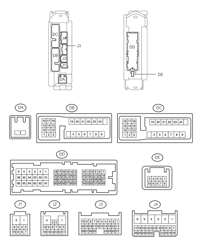
CHECK MAIN BODY ECU (DRIVER SIDE JUNCTION BLOCK)
4.76,2.635 5.563,2.635
false
2.333,1.625 2.688,1.625
false
5.573,3.74 5.792,3.917
0.219,0.177
10
false
DC
2.469,3.74 2.677,3.917
0.208,0.177
10
false
DB
0.646,3.729 0.854,3.906
0.208,0.177
10
false
DA
2.115,5.385 2.333,5.563
0.219,0.177
10
false
DD
5.521,5.5 5.729,5.677
0.208,0.177
10
false
DE
0.646,7.156 0.813,7.333
0.167,0.177
10
false
J1
1.875,7.167 2.042,7.344
0.167,0.177
10
false
J2
3.521,7.167 3.688,7.344
0.167,0.177
10
false
J3
5.479,7.167 5.646,7.344
0.167,0.177
10
false
J4
1.885,1.885 2.094,2.063
0.208,0.177
10
false
DB
1.875,1.135 2.094,1.313
0.219,0.177
10
false
DC
2.208,2.229 2.375,2.406
0.167,0.177
10
false
J1
2.219,1.99 2.385,2.167
0.167,0.177
10
false
J2
2.74,1.542 2.906,1.719
0.167,0.177
10
false
J3
2.208,1.271 2.375,1.448
0.167,0.177
10
false
J4
2.125,2.729 2.333,2.906
0.208,0.177
10
false
DA
4.615,1.583 4.833,1.76
0.219,0.177
10
false
DD
5.635,2.563 5.844,2.74
0.208,0.177
10
false
DE
a.
Disconnect the J3, J4, DA and DD ECU connectors.
b.
Measure the voltage and resistance according to the value(s) in the table below.
| Terminal No. (Symbols) | Wiring Color | Terminal Description | Condition | Specified Condition |
|---|---|---|---|---|
| DA-1 (ACC) - Body ground | B - Body ground | ACC power supply | Always | 11 to 14 V |
| DA-1 (IG) - Body ground | B - Body ground | IG power supply | Always | 11 to 14 V |
| DB-21 (GND1) - Body ground | B - Body ground | Body ground | Always | Below 1 Ω |
| DB-21 (GND2) - Body ground | B - Body ground | Body ground | Always | Below 1 Ω |
| J4-24 (DCTY) - Body ground | GR - Body ground | Front door courtesy light switch LH signal | Front door LH open | Below 1 Ω |
| Front door LH closed | 10 kΩ or higher | |||
| J3-21 (PCTY) - Body ground | W - Body ground | Front door courtesy light switch RH signal | Front door RH open | Below 1 Ω |
| Front door RH closed | 10 kΩ or higher |
If the result is not as specified, there may be a malfunction on the wire harness side.