Home › Vehicle Interior › WINDOW / GLASS › BACK WINDOW GLASS(for Regular Cab and Double Cab)
RM27M0U _58 Vehicle Interior _049161 WINDOW / GLASS _0234467 BACK WINDOW GLASS(for Regular Cab and Double Cab) G

WINDOW / GLASS  BACK WINDOW GLASS(for Regular Cab and Double Cab)  INSPECTION  


PROCEDURE

Hide 85710J 1.INSPECT POWER WINDOW REGULATOR MOTOR ASSEMBLY (for Power Slide Type)
B227090E02
1.917,2.75 2.094,2.135 2.094,2.135 2.198,2.135 false 2.771,3.125 3.042,3.125 3.042,3.125 3.042,4.01 false 2.25,2.073 3.021,2.271 0.771,0.198 10 false Motor Gear 1.26,3.708 1.927,3.906 0.667,0.198 10 false Clockwise 2.177,4.01 3.302,4.208 1.125,0.198 10 false Counterclockwise 0.302,0.125 2.656,0.667 2.354,0.542 10 false Component with harness connected: (Power Window Regulator Motor Assembly)

a.

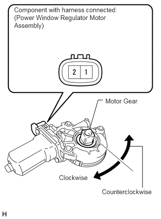
Check the operation of the power window regulator motor.

i.

Apply battery voltage to the power window regulator motor.


ii.

Check that the motor gear rotates smoothly as follows.

OK:
Measurement Condition Specified Condition
Battery positive (+) → 2
Battery negative (-) → 1
Motor gear rotates clockwise
Battery positive (+) → 1
Battery negative (-) → 2
Motor gear rotates counterclockwise


If the result is not as specified, replace the regulator motor.


Hide 85939 2.INSPECT NO. 1 BACK POWER WINDOW RELAY (except 3UR-FBE)

a.

Remove the power window relay from the engine room relay block.

b.
B106753E16
2.49,0.844 2.49,0.615 false 2.854,1.177 3.042,1.177 false 2.49,1.51 2.49,1.708 false 2.073,1.198 2.073,1.729 false 2.479,1.031 1.802,1.031 false 0.813,0.104 0.906,0.302 0.094,0.198 10 false 4 0.302,0.781 0.396,0.979 0.094,0.198 10 false 5 1.281,0.802 1.375,1 0.094,0.198 10 false 3 0.333,1.594 0.427,1.792 0.094,0.198 10 false 1 1.292,1.583 1.385,1.781 0.094,0.198 10 false 2 1.677,0.917 1.771,1.115 0.094,0.198 10 false 4 3.052,1.052 3.146,1.25 0.094,0.198 10 false 5 2.031,1.74 2.125,1.938 0.094,0.198 10 false 3 2.448,0.396 2.542,0.594 0.094,0.198 10 false 1 2.458,1.74 2.552,1.938 0.094,0.198 10 false 2

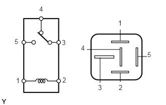
Measure the resistance according to the value(s) in the table below.

Standard resistance:
Tester Connection Condition Specified Condition
3 - 4 When battery voltage is not applied between terminals 1 and 2 Below 1 Ω
When battery voltage is applied between terminals 1 and 2 10 kΩ or higher
3 - 5 When battery voltage is not applied between terminals 1 and 2 10 kΩ or higher
When battery voltage is applied between terminals 1 and 2 Below 1 Ω


If the result is not as specified, replace the relay.


Hide 85939 3.INSPECT NO. 2 BACK POWER WINDOW RELAY

a.

Remove the power window relay from the engine room relay block.


b.
B106753E16
2.49,0.844 2.49,0.615 false 2.854,1.177 3.042,1.177 false 2.49,1.51 2.49,1.708 false 2.073,1.198 2.073,1.729 false 2.479,1.031 1.802,1.031 false 0.813,0.104 0.906,0.302 0.094,0.198 10 false 4 0.302,0.781 0.396,0.979 0.094,0.198 10 false 5 1.281,0.802 1.375,1 0.094,0.198 10 false 3 0.333,1.594 0.427,1.792 0.094,0.198 10 false 1 1.292,1.583 1.385,1.781 0.094,0.198 10 false 2 1.677,0.917 1.771,1.115 0.094,0.198 10 false 4 3.052,1.052 3.146,1.25 0.094,0.198 10 false 5 2.031,1.74 2.125,1.938 0.094,0.198 10 false 3 2.448,0.396 2.542,0.594 0.094,0.198 10 false 1 2.458,1.74 2.552,1.938 0.094,0.198 10 false 2

Measure the resistance according to the value(s) in the table below.

Standard resistance:
Tester Connection Condition Specified Condition
3 - 4 When battery voltage is not applied between terminals 1 and 2 Below 1 Ω
When battery voltage is applied between terminals 1 and 2 10 kΩ or higher
3 - 5 When battery voltage is not applied between terminals 1 and 2 10 kΩ or higher
When battery voltage is applied between terminals 1 and 2 Below 1 Ω


If the result is not as specified, replace the relay.


Hide 85939 4.INSPECT NO. 3 BACK POWER WINDOW RELAY (for 3UR-FBE)

a.

Remove the power window relay from the engine room relay block.


b.
B106753E16
2.49,0.844 2.49,0.615 false 2.854,1.177 3.042,1.177 false 2.49,1.51 2.49,1.708 false 2.073,1.198 2.073,1.729 false 2.479,1.031 1.802,1.031 false 0.813,0.104 0.906,0.302 0.094,0.198 10 false 4 0.302,0.781 0.396,0.979 0.094,0.198 10 false 5 1.281,0.802 1.375,1 0.094,0.198 10 false 3 0.333,1.594 0.427,1.792 0.094,0.198 10 false 1 1.292,1.583 1.385,1.781 0.094,0.198 10 false 2 1.677,0.917 1.771,1.115 0.094,0.198 10 false 4 3.052,1.052 3.146,1.25 0.094,0.198 10 false 5 2.031,1.74 2.125,1.938 0.094,0.198 10 false 3 2.448,0.396 2.542,0.594 0.094,0.198 10 false 1 2.458,1.74 2.552,1.938 0.094,0.198 10 false 2

Measure the resistance according to the value(s) in the table below.

Standard resistance:
Tester Connection Condition Specified Condition
3 - 4 When battery voltage is not applied between terminals 1 and 2 Below 1 Ω
When battery voltage is applied between terminals 1 and 2 10 kΩ or higher
3 - 5 When battery voltage is not applied between terminals 1 and 2 10 kΩ or higher
When battery voltage is applied between terminals 1 and 2 Below 1 Ω


If the result is not as specified, replace the relay.