SEAT SEAT HEATER SYSTEM TERMINALS OF ECU
CHECK POWER DISTRIBUTION BOX ASSEMBLY
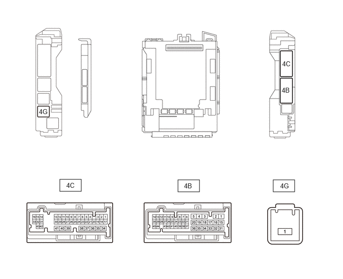
Remove the power distribution box assembly.
Click herePower Source / Network>POWER DISTRIBUTION>MAIN BODY ECU>REMOVAL
Reconnect the power distribution box assembly connectors.
Measure the voltage and resistance according to the value(s) in the table below.
- Standard:
Terminal No.
(Symbol)Terminal Description Condition Specified Condition 4G-1 - Body ground Power source Ignition switch off 11 to 14 V 4C-25 - Body ground Ground Always Below 1 Ω 4B-6 - Body ground Seat heater switch LH signal ·Ignition switch ON
·Seat heater switch LH off
Below 1 Ω ·Ignition switch ON
·Seat heater switch LH on
11 to 14 V 4B-7 - Body ground Seat heater switch RH signal ·Ignition switch ON
·Seat heater switch RH off
Below 1 Ω ·Ignition switch ON
·Seat heater switch RH on
11 to 14 V 4C-39 - Body ground Seat heater LH drive signal Seat heater LH is not operating Below 1 Ω Seat heater LH is operating 11 to 14 V 4C-40 - Body ground Seat heater RH drive signal Seat heater RH is not operating Below 1 Ω Seat heater RH is operating 11 to 14 V
CHECK AIR CONDITIONING AMPLIFIER ASSEMBLY (for Automatic Air Conditioning System HV Model)
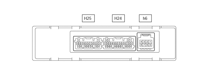
Disconnect the H24 air conditioning amplifier assembly connector.
Measure the voltage and resistance according to the value(s) in the table below.
- Standard:
Terminal No.
(Symbol)Terminal Description Condition Specified Condition H24-5 (B) - H24-17 (GND) Power source Ignition switch off 11 to 14 V H24-6 (IG+) - H24-17 (GND) Power source (IG) Ignition switch ON 11 to 14 V Ignition switch off Below 1 V H24-17 (GND) - Body ground Ground for main power supply Always Below 1 Ω H24-26 (SHIN) - H24-17 (GND) Driver side seat heater switch operation signal ·Ignition switch ON
·Seat heater switch RH off
Below 1 V ·Ignition switch ON
·Seat heater switch RH on
11 to 14 V