HEATING / AIR CONDITIONING AIR CONDITIONING PANEL(for Manual Air Conditioning System) INSTALLATION
CAUTION / NOTICE / HINT
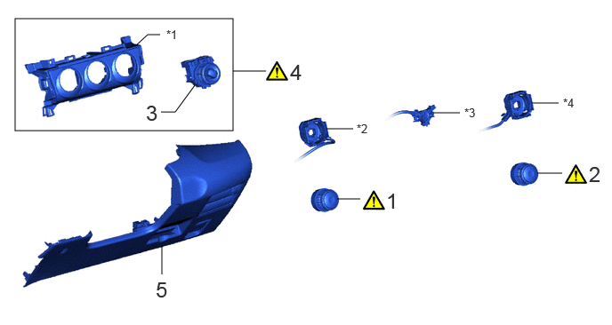
| Procedure | Part Name Code | 
|

|

|
|
|---|---|---|---|---|---|
| 1 | NO. 1 HEATER CONTROL SUB-ASSEMBLY | 55901D | ( ) |
- | - |
| 2 | NO. 3 HEATER CONTROL SUB-ASSEMBLY | 55903A | ()
|
- | - |
| 3 | NO. 2 HEATER CONTROL SUB-ASSEMBLY | 55902E | - | - | - |
| 4 | INSTRUMENT CLUSTER FINISH LOWER CENTER PANEL SUB-ASSEMBLY | 55406B | ()
|
- | - |
| 5 | LOWER INSTRUMENT PANEL FINISH PANEL ASSEMBLY | 55480D | - | - | - |
| *1 | INSTRUMENT CLUSTER FINISH LOWER CENTER PANEL SUB-ASSEMBLY | *2 | DEFROSTER DAMPER CONTROL CABLE SUB-ASSEMBLY |
| *3 | AIR INLET DAMPER CONTROL CABLE SUB-ASSEMBLY | *4 | AIR MIX DAMPER CONTROL CABLE SUB-ASSEMBLY |
PROCEDURE

 55901D
1.INSTALL NO. 1 HEATER CONTROL SUB-ASSEMBLY
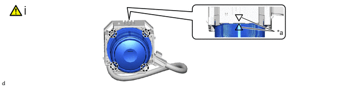
| *a | Alignment Mark | - | - |
Engage the claws to install the No. 1 heater control sub-assembly as shown in the illustration.
- NOTICE:
-
Before installing the No. 1 heater control sub-assembly, align the alignment mark of the dial side with the alignment mark of the cable side as shown in the illustration.
55903A
2.INSTALL NO. 3 HEATER CONTROL SUB-ASSEMBLY
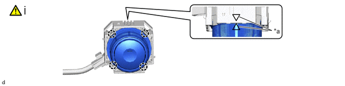
| *a | Alignment Mark | - | - |
Engage the claws to install the No. 3 heater control sub-assembly as shown in the illustration.
- NOTICE:
-
Before installing the No. 3 heater control sub-assembly, align the alignment mark of the dial side with the alignment mark of the cable side as shown in the illustration.
55902E
3.INSTALL NO. 2 HEATER CONTROL SUB-ASSEMBLY
55406B
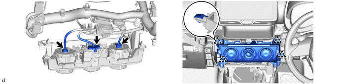
4.INSTALL INSTRUMENT CLUSTER FINISH LOWER CENTER PANEL SUB-ASSEMBLY
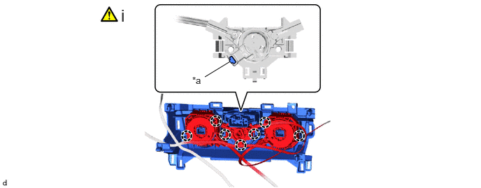
| *a | Alignment Mark | - | - |
Engage the claws to install the instrument cluster finish lower center panel sub-assembly as shown in the illustration.
- NOTICE:
-
Before installing the instrument cluster finish lower center panel sub-assembly, align the alignment mark of the dial side with the alignment mark of the cable side as shown in the illustration.
55480D
5.INSTALL LOWER INSTRUMENT PANEL FINISH PANEL ASSEMBLY